 |
| Figure 1: A coaxial cable presents high impedance at low frequencies but acts as a transmission line at higher frequencies |
You need to test, we're here to help.
You need to test, we're here to help.
19 December 2018
Using 50-Ohm Coax From DUT to Oscilloscope
12 December 2018
Squeezing More Bandwidth From a 10x Passive Probe
 |
| Figure 1: Shown is a comparison of inherent oscilloscope noise and noise at the shorted tip of a 10x passive probe |
28 November 2018
10x Passive Probes and Cable Reflections
 |
| Figure 1: With unequal impedances at either end of the coax, are cable reflections a concern in 10x passive probes? |
08 November 2018
How Tip Inductance Impacts a Probing System's Bandwidth
01 November 2018
How Equalization Works in 10x Passive Probes
 |
| Figure 1: The adjustable equalization circuit on the oscilloscope end of the coaxial cable compensates for the 10x passive probe's inherent low-pass filter characteristics |
24 October 2018
Secrets of the 10x Passive Probe
 |
| Figure 1: The 10x passive probe becomes a better measurement tool when we understand its limitations |
10 October 2018
Putting Probes in Perspective
 |
| Figure 1: Probe, cable, and oscilloscope form a system that makes or breaks the accuracy of signal acquisitions |
13 September 2018
Decision Feedback Equalization
 |
| Figure 1: DFE filter output is based on a linear combination of previous bit decisions |
30 August 2018
The Causes of Ground Bounce and How To Avoid It
 |
| Figure 1: This cross section of a 100-MHz microstrip transmission line shows us how a return path should look |
29 August 2018
A Walk-Through of Ground-Bounce Measurements
 |
| Figure 1: The trigger pulse from the MCU is one clock cycle in width |
16 August 2018
More on Quiet-Low I/O Drivers and Ground Bounce
 |
| Figure 1: To configure an I/O driver as a quiet-low line, its output is connected directly to Vss on the die |
07 August 2018
About Ground Bounce and How to Measure It
 |
| Figure 1: Shown are five I/O drivers within a package driving signal lines on a PC board |
23 July 2018
Feed-Forward Equalization
 |
| Figure 1: FFE creates a number of delayed versions of the input signal that are then added back to the signal with proper weights |
17 July 2018
Continuous Time Linear Equalization
 |
| Figure 1: A CTLE implementation at the receiver end of a serial-data channel seeks to boost higher frequencies while not boosting noise any more than necessary |
10 July 2018
Serial-Data Channel Emulation and S Parameters
 |
| Figure 1: Higher data rates + "same old" channel media = degraded signal quality at receiver |
29 June 2018
The Effects of De-Emphasis on Eye Diagrams
 |
| Figure 1: This eye diagram of a serial-data stream as measured at the receiver shows the effect a lossy channel has on signal quality |
27 June 2018
Introduction to Channel Equalization
 |
| Figure 1: Transmit pre-emphasis pre-distorts signals in anticipation of the channel's effects |
19 June 2018
Rise-Time Degradation and ISI Jitter
 |
| Figure 1: Shown are the signals from two extreme bit patterns overlaid on top of each other with no interconnect in the channel |
13 June 2018
Inter-Symbol Interference (or Leaky Bits)
 |
| Figure 1: Inter-symbol interference, or ISI jitter, is the result of information from one bit "leaking" to subsequent bits |
12 June 2018
How Much Transmission-Line Loss is Too Much?
 |
| Figure 1: This plot represents the differential insertion-loss profile for a 20" FR-4 microstrip trace |
06 June 2018
A Look at Transmission-Line Losses
 |
| Figure 1: Using a 3D field solver to simulate a differential trace |
05 June 2018
Introduction to Debugging High-Speed Serial Links
 |
| Figure 1: These images depict the degradation of serial data traffic as it makes its way from transmitter to receiver |
18 May 2018
Examples of IoT DDR Debug Scenarios
 |
| Figure 1: Using the oscilloscope's Track math function can help pin down timing anomalies |
15 May 2018
Debugging DDR Memory on IoT Devices
 |
| Figure 1: Embedded systems such as IoT devices often require chip interposers to gain access to signal lines on DDR memory |
10 May 2018
Debugging Ethernet, SATA, and PCIe for IoT Devices
 |
| Figure 1: A generic IoT block diagram shows serial-data links in blue |
08 May 2018
Debugging CANbus For IoT Devices
 |
| Figure 1: Temperature data from thermocouples is shown both encoded and decoded on the oscilloscope's display |
04 May 2018
Debugging Low-Speed Serial Data on IoT Devices
 |
| Figure 1: Serial-data links handle traffic between ICs and peripheral devices in the IoT world |
02 May 2018
Acquiring and Characterizing IoT Sensor Signals
 |
| Figure 1: IoT devices use many sensors to collect data about their ambient environment |
30 April 2018
Investigating IoT Wireless Signals (Part II)
 |
| Figure 1: This screen capture depicts frequency demodulation and subsequent Manchester decoding of the bit stream |
23 April 2018
Investigating IoT Wireless Signals
 |
| Figure 1: Many IoT devices accept wireless antennas using U.FL connectors |
19 April 2018
IoT Digital Power Management and Power Integrity
 |
| Figure 1: The half-bridge output current from each DC-DC phase is known as the inductor current |
16 April 2018
Anatomy of an IoT Device
 |
| Figure 1: IoTs include SOCs, DDR, DPM ICs, wireless, and MCUs |
04 April 2018
Debugging the IoT
 |
| Figure 1: Chances are you're already using the IoT in various ways |
15 March 2018
An Example of Three-Phase Power Measurements
 |
| Figure 1: Screen capture of a 10-s acquisition of AC input and PWM output of a 480-V motor drive |
14 March 2018
Three-Phase Power Calculations
 |
| Figure 1: Three-phase power calculations entail summing of the individual phases's power calculations |
13 March 2018
Power Calculations for Distorted Waveforms
 |
| Figure 1: The sum of many sine waves, of varying amplitudes and frequencies, comprises the rough- looking square wave shown in red |
09 March 2018
Power Calculations for Pure Sine Waves
 |
| Figure 1: For a purely resistive load, power = voltage * current, with both vectors in phase |
Back to Basics: AC Sinusoidal Line Current
 |
| Figure 1: A single-phase AC current vector rotates at 50 or 60 Hz |
02 March 2018
More Basics of Three-Phase AC Sinusoidal Voltages
 |
| Figure 1: In the Wye three-phase connection, neutral is present but sometimes inaccessible |
01 March 2018
Transmission Lines (Part V): Reverse-Engineering the DUT
 |
| Figure 1: Every DUT can be thought of as a Thevenin voltage source with some internal resistance |
27 February 2018
Transmission Lines (Part IV): More Essential Principles
 |
| Figure 1: The return current in a transmission line is as important as the signal current |
26 February 2018
Transmission Lines (Part III): Essential Principles
 |
| Figure 1: All interconnects are transmission lines with a signal path and a return path (not ground) |
23 February 2018
Transmission Lines (Part II): More on Bandwidth vs. Rise Time
 |
| Figure 1: In the frequency domain (right), a near-ideal square wave displays predictable 1/f amplitude dropoff |
20 February 2018
Transmission Lines (Part I): Introduction
 |
| Figure 1: All oscilloscopes have a Cal output like the one pictured here |
16 February 2018
Probing Techniques and Tradeoffs (Part XI): Non-Ideal Situations
 |
| Figure 1: VP@Rcvr builds a transmission-line model to virtually move less-than-ideal probing points |
12 February 2018
Probing Techniques and Tradeoffs (Part X): More Best Practices
 |
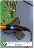
| Figure 1: Chip clips; they're not just for snacks anymore |
09 February 2018
Probing Techniques and Tradeoffs (Part IX): Best Practices
 |
| Figure 1: The typical manner of using a hands-free probe holder can cause issues |
08 February 2018
Probing Techniques and Tradeoffs (Part VIII): Gain/Attenuation vs. Noise
 |
| Figure 1: Noise comparison of a Teledyne LeCroy D1605 probe and a competing model |
06 February 2018
Probing Techniques and Tradeoffs (Part VII): More on Dynamic Range
 |
| Figure 1: Input offset range is how much differential offset a probe can apply to an input signal to bring it within its differential-mode output range |
05 February 2018
Getting The Most Out Of Your Oscilloscope: Physical-Layer Tools
 |
| Figure 1: Trigger dialog boxes will match the protocol of interest |
Subscribe to:
Comments (Atom)
