 |
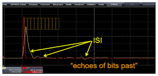
| Figure 1: Inter-symbol interference, or ISI jitter, is the result of information from one bit "leaking" to subsequent bits |
There are multiple causes of ISI, or, as it's sometimes known, ISI jitter. The first is reflection noise. Say, for example, we have a single unit interval (UI) or pulse with a width of 200 ps traversing a data channel. This channel extends from a daughter card through a backplane to another daughter card with some SMA connectors along the way.
When we look at the signal pulse at the receiver end of the channel, one thing that's immediately apparent is a drop in amplitude, which we would expect. We also note some rise-time degradation as well as some ringing on the received signal. If we were to overlay the transmitted and received pulses, we would see what appears to be "echoes" of the bit where the subsequent bits would be (Figure 1).
 |
| Figure 2: Group delay dispersion, another root cause of ISI jitter, occurs because of the varying propagation rates of different frequency components of the signal |
A second root cause of ISI jitter is group delay dispersion. If our channel has no impedance discontinuities, and we inject the same single-pulse signal into it, we would still see pulse broadening and dispersion through the next few bits. Group delay dispersion happens because different frequencies propagate through the same material at different velocities.
In Figure 2, the yellow trace is the channel input with the channel output in red. Obviously, the pulse is much wider and spread out, almost reaching into the next bit in the sequence. The correlated clock trace gives you an idea of how wide each UI is. This spreading of the signal at the far end of the channel is entirely due to group delay dispersion and not to reflections.
 |
| Figure 3: A frequency-domain view illustrates the greater effects of frequency-dependent losses at the high end of the spectrum |
However, as the signal travels through the channel, the channel's attenuation profile reduces signal energy across the frequency band; there is a different attenuation value at each frequency point. The resulting spectrum at the output of the channel shows the frequency content of the data stream as it hits the receiver. We can see that some energy has been completely lost. The third harmonic is attenuated to a much greater degree than the second harmonic or fundamental. In the time domain, this results in ISI. It's the signature effect of frequency-dependent losses, which increase with frequency. Phase dispersion, which is not illustrated (or discussed) here, also contributes to the channel losses.
We'll continue with the topic of inter-symbol interference in our next post, and also pivot toward the means of compensating for channel losses: equalization.
Previous posts in this series:
Introduction to Debugging High-Speed Serial Links
A Look at Transmission-Line Losses
How Much Transmission-Line Loss is Too Much?
No comments:
Post a Comment