 |
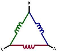
| Figure 1: In the Wye three-phase connection, neutral is present but sometimes inaccessible |
There are different connection configurations for three-phase lines, two of these being the Wye (Y) and Delta (Δ) configurations. The former (Figure 1) is likely the most common configuration. In the Wye connection, you'll see three coils with a terminal and neutral interrupted by a coil as in a transformer. Neutral is always present in the Wye connection but in many cases is not accessible.
 |
| Figure 2: Delta three-phase connections typically do not make neutral present in the winding |
Line-Line Voltage Measurements
It's important to understand that you'll often see voltage referred to as VAC, but what is actually present is VRMS. AC-voltage ratings are always for line-line voltage values; the typical value in the U.S. is 480 V.
 |
| Figure 3: This graph depicts the line-line measurements of the three phases of a 480-V utility voltage |
For three-phase systems, you can calculate the peak and peak-to-peak voltages. For the former,
VPEAK(L-L) = √2 * VL-L
while for the latter,
VPEAK(L-L) = 2 * VPEAK(L-L)
Figure 3 depicts a three-phase "utility" voltage of 480 VAC, with all three phases shown as line-line voltages. In this case, the peak voltage is about 680 V and the peak-to-peak voltage is near twice that at about 1400 V.
Line-Neutral Voltage Measurements
 |
| Figure 4: This graph depicts the line-neutral measurements of the three phases of a 480-V utility voltage |
- VLINE-NEUTRAL (VL-N) = VL-L/√3 (in this case, 277 VAC RMS)
- VPEAK = √2 * VL-N (in this case, 392 V)
- VPK-PK = 2 * VPEAK
Even though a configuration as such is described as a 480-V AC system, in this case it's actually 277 V (Figure 4). If you should see or hear a reference to a "480 277," it's because the reference is to line-line or line-neutral. The calculations shown above are much like the line-line calculations, so the peak voltage is almost 400 V and peak-to-peak voltage almost 800 V.
If all three phases are rectified, filtered, and summed, you get a DC value of 679 V using:
VDC= √2 * VL-N * √3 = VPEAK * √3
The practical maximum filtered DC bus voltage is less than the sum of the vectors. Note that Figure 4 depicts the DC added after rectification but does not show it filtered.
An eyeball comparison of Figures 3 and 4 (line-line and line-neutral voltages, respectively) shows the magnitude difference between them. There's also a slight phase difference of about 30°.
You may have heard references to utility AC voltage classes, which are defined for standards organizations such as ANSI in the United States and IEC in Europe. The following definitions are per ANSI C84.1-1989.
First, the low-voltage 50-V class isn't really a "class" as such but rather a safety rating. Fifty volts is considered safe for exposure to uninsulated conductors.
The low-voltage 600-V class is a distribution voltage class that covers:
- Residential, small commercial single-phase voltages of 100/110/120 V, 208 V, and 220/240 V
- Three-phase voltages of 380/400 V, 440/480 V, 575/600 V, and a maximum of 690 V (600 V + 15%)
The definition of medium voltages for power generation, distribution, and sub-transmission comprises "classes" of 5 kV, 15 kV, 25 kV, 35 kV, and 69 kV.
In an upcoming post, we'll begin looking at AC sinusoidal line currents.
Previous posts in this series:
Back to Basics: The Fundamentals of Power
Back to Basics: Fundamentals of AC Line Power (Part II)
Back to Basics: Three-Phase Sinusoidal Voltages
No comments:
Post a Comment