 |
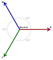
| Figure 1: Three-phase AC voltages consist of three voltage vectors |
As mentioned above, three-phase AC sinusoidal voltages consist of three voltage vectors (Figure 1). By definition, these vectors are "balanced," being separated by 120° in phase, and being of equal magnitude. Moreover, the sum of all three voltages is equal to zero volts at the central neutral point.
Typically, the three phases are designated A, B, and C. However, you may see other conventions used for these designations, such as 1, 2, and 3; L1, L2, and L3; and R, S, and T.
 |
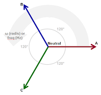
| Figure 2: Vectors rotate at a given frequency with constant phase separation |
The resulting time-varying, "rotating" voltage vectors appear as three sinusoidal waveforms. They are separated by 120° in phase and are of equal peak amplitude.
The voltage value is calculated as: Vx * sin(α), where Vx is the magnitude of the phase voltage vector and α is the angle of rotation (in radians).
There are a variety of reasons for using three-phase AC voltage:
- It's more efficient to generate power with three-phase generators
- It's easier to manufacture high-power transformers and motors
- Superior control capabilities for low-power motors
 |
| Figure 3: There are two ways to measure three-phase voltages: line-to-line and line-to-neutral |
Note that the line-to-line vectors are longer than the line-to-neutral vectors. Thus, magnitudes of line-to-line voltages are typically larger than line-to-neutral voltages. It's more common to probe and acquire line-to-line voltages, because while a neutral point may not always be present, there will always be the three lines. Also, line-to-line measurements may be converted to line-to-neutral values and vice versa. The differences between them boil down to a 30° difference in phase and a magnitude difference of √3.
Next time, we'll look at the ways in which three-phase connections can be made as well as more details of line-to-line and line-to-neutral measurements.
No comments:
Post a Comment