You need to test, we're here to help.

You need to test, we're here to help.
Showing posts with label ISI. Show all posts

10 October 2022

Oscilloscope Testing of 10Base-T1S Automotive Ethernet Signal Integrity

Eye diagram generated from decoded 10Base-T1S signal
Figure 1. The 10Base-T1S TDME option features
easy eye diagram creation for signal integrity analysis.
Click on any image to enlarge it.
In addition to special serial data bus measurements of 10Base-T1S signals, the 10Base-T1S Trigger, Decode, Measure/Graph & Eye Diagram (TDME) option automates the generation and display of eye diagrams on Teledyne LeCroy oscilloscopes. Eye diagrams are an important element of serial data analysis, used to understand the signal integrity of the communications network. 

The eye diagram is a general-purpose tool for analyzing serial digital communications signals. It shows the effects of additive vertical noise, horizontal jitter, duty cycle distortion, inter-symbol interference, and crosstalk on a serial data stream. 

The eye diagram is formed by overlaying repetitive occurrences of slightly more than a single clock period (UI) of a serial data signal on a persistence display which shows the accumulated history of multiple acquisitions, as shown in Figure 1.

Due to the use of Differential Manchester encoding (DME), the 10Base-T1S eye is formed with twice the signal clock rate. The signal shown has a symbol rate of 12.5 Mbps and the eye is clocked at 25 Mbps. 

13 September 2018

Decision Feedback Equalization

DFE filter output is based on a linear combination of previous bit decisions
Figure 1: DFE filter output is based on
a linear combination of previous bit
decisions
In debugging high-speed serial links, one must be cognizant of various forms of equalization that might be used in the link to compensate for signal degradation in the channel. Inter-symbol interference (ISI), attenuation, impedance mismatches, and insertion losses can all contribute to this loss of signal quality. To combat these effects, designers implement techniques such as continuous time linear equalization and feed-forward equalization.

17 July 2018

Continuous Time Linear Equalization

A CTLE implementation at the receiver end of a serial-data channel seeks to boost higher frequencies while not boosting noise any more than necessary
Figure 1: A CTLE implementation at the receiver end of a
serial-data channel seeks to boost higher frequencies while
not boosting noise any more than necessary
We've been looking at the broad topic of debugging high-speed serial links, and in that context, we're also touching on ways to improve signal performance on the receiver side. One of those ways is to implement continuous time linear equalization (CTLE).

10 July 2018

Serial-Data Channel Emulation and S Parameters

Higher data rates + "same old" channel media = degraded signal quality at receiver
Figure 1: Higher data rates + "same old" channel media
= degraded signal quality at receiver
Serial data rates have risen but propagation media for the channel remain unchanged, and that results in greater attenuation to the frequencies of interest. We could ignore these losses at lower frequencies, but now that rise times are so much faster, that's not an option. Channel effects now intrude into design margins to the point where eyes deteriorate and bit-error rates become unacceptable.

27 June 2018

Introduction to Channel Equalization

Transmit pre-emphasis pre-distorts signals in anticipation of the channel's effects
Figure 1: Transmit pre-emphasis pre-distorts signals
in anticipation of the channel's effects
A number of factors can cause degradation of performance in a high-speed serial data link. Among them are inter-symbol interference (ISI) jitter, attenuation, reflections due to impedance mismatches, and insertion losses, to name a few. But fear not: There are techniques one may use to compensate for these losses known as equalization. We'll review the basics of channel equalization in today's post.

19 June 2018

Rise-Time Degradation and ISI Jitter

Shown are the signals from two extreme bit patterns overlaid on top of each other with no interconnect in the channel
Figure 1: Shown are the signals from two extreme bit patterns
overlaid on top of each other with no interconnect in the channel
In discussing inter-symbol interference (ISI), the phenomenon in which information "leaks" from one bit to subsequent bits, we've identified a couple of root causes of ISI jitter. The first is reflection losses caused by impedance discontinuities, while the second is group delay dispersion, a consequence of the differing propagation speeds of different frequencies through a given material. We looked at these forms of distortion in both the time and frequency domains.

13 June 2018

Inter-Symbol Interference (or Leaky Bits)

Inter-symbol interference, or ISI jitter, is the result of information from one bit "leaking" to subsequent bits
Figure 1: Inter-symbol interference, or ISI jitter, is the result
of information from one bit "leaking" to subsequent bits
In reviewing the subject of debugging high-speed serial links, one important aspect of signal integrity we must touch on is inter-symbol interference (ISI). ISI is the phenomenon in which information from one bit "leaks" to some subsequent number of bits.

28 May 2015

The History of Jitter (Part V)

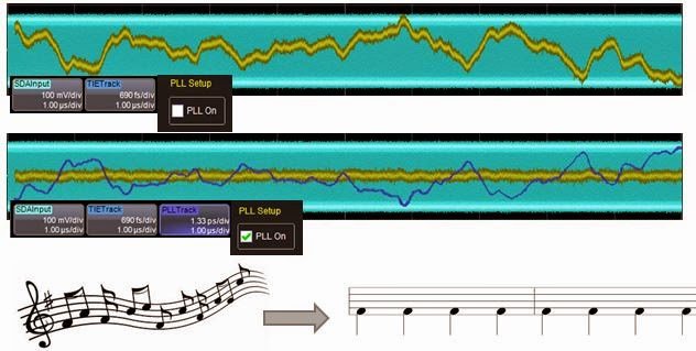
Applying PLLs for clock-data recovery is not unlike tapping your feet to the beat of music
Figure 1: Applying PLLs for clock-data recovery is not
unlike tapping your feet to the beat of music
A milestone in the history of jitter measurement came in the 1990s with receivers that could reveal the slowly varying component of jitter that became evident in time-interval error (TIE) tracks. That led to the advent of using phase-locked loops (PLLs) for clock-data recovery. In turn, PLLs opened new horizons in jitter analysis.

22 January 2014

The Components of Total Jitter

Figure 1: An overview of the jitter hierarchy, or "jitter tree," showing the various elements that make up total jitter
Figure 1: An overview of the jitter hierarchy,
or "jitter tree," showing the various elements
that make up total jitter
In an earlier post, we began looking at the topic of jitter, a topic of keen interest to anyone working with high-speed serial communications or the components of such a system, including transmitters, receivers, and data channels. To gain an understanding of jitter, an important first step is getting to know a little about the various categories that comprise total jitter.