You need to test, we're here to help.

You need to test, we're here to help.
Showing posts with label finite impulse response. Show all posts

27 June 2018

Introduction to Channel Equalization

Transmit pre-emphasis pre-distorts signals in anticipation of the channel's effects
Figure 1: Transmit pre-emphasis pre-distorts signals
in anticipation of the channel's effects
A number of factors can cause degradation of performance in a high-speed serial data link. Among them are inter-symbol interference (ISI) jitter, attenuation, reflections due to impedance mismatches, and insertion losses, to name a few. But fear not: There are techniques one may use to compensate for these losses known as equalization. We'll review the basics of channel equalization in today's post.

16 January 2018

An Under-The-Hood View of PCIe 3.0 Link Training (Part II)

A diagrammatic view of the PCIe 3.0 dynamic link training process
Figure 1: A diagrammatic view of the
PCIe 3.0 dynamic link training process
Our last post in this series began examining the recovery.equalization process of PCIe 3.0 dynamic link training, beginning with Phases 0 and 1 of the process (Figure 1). Next, we will move on to take a closer look at Phases 2 and 3, where we'll see what can happen with devices in which the algorithms are not up to par. Namely, issues such as packet errors, dropped packets, and link retraining at lower data rates than 8 Gb/s.

14 November 2014

An Under-the-Hood View of PCIe 3.0 Link Training (Part I)

An overview of the elements of PCIe 3.0 dynamic link equalization
Figure 1: An overview of the elements of PCIe 3.0
dynamic link equalization
Now that we've looked at the basics of PCIe 3.0 dynamic link equalization and at some of the particulars of de-emphasis and preshoot, it's time to dive a little deeper into what actually happens in the link training process. It all happens in the blink of an eye but there's enough going on to warrant some dissection.

09 April 2014

Applying Multi-Stage, Multi-Rate Digital Filtering
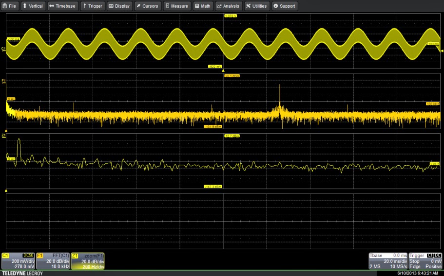
63-kHz signal with 60-Hz component
Figure 1: The input signal shows both the desired 63-kHz signal
along with a 60-Hz component. Zoom trace Z1 shows the
60-Hz component in detail.
A while back, we posted some basics on how to apply digital filters to sort out signals with undesirable elements riding on top of them, i.e. a square wave that's being corrupted by a sinusoidal signal creeping in from somewhere in your system design. Now, let's look at how to extend the range of cutoff frequencies for digital filters, allowing them to be used even more effectively.