You need to test, we're here to help.

You need to test, we're here to help.
Showing posts with label low-pass filter. Show all posts

25 July 2022

Signal and Power Integrity Tutorial: How PDN Design Affects Board-level Noise

Figure 1. Oscilloscope traces resulting from  measuring a 3.3. V power rail with a 10x probe versus a coaxial connection, with an adjacent 10x probe acting as an RF antenna.
Figure 1. Oscilloscope traces resulting from 
measuring a 3.3. V power rail with a 10x probe
versus a coaxial connection, with an
adjacent 10x probe acting as an RF antenna.
By Prof. Eric Bogatin,
Teledyne LeCroy Fellow

Excerpted by permission from the Signal Integrity Journal article, Measuring Only Board-level Power Rail Noise May Be Misleading

In our blog, we’ve presented a lot about the impact of the interconnect on oscilloscope measurements, and how where you probe can be as important as how you probe. This article is an excellent demonstration of those very principles.

************************************

Power rail measurements are important because they can identify potential sources of noise before they become a problem. However, measuring only the power rail noise at the board-level may be a misleading indication of the noise the die actually sees. 

Best Practices for Power Integrity Measurements

Measuring a power rail on a board seems like a simple task. Like all measurements, it is easy to get a waveform on the oscilloscope’s screen, but it is difficult to have confidence you have eliminated the measurement artifacts and have a realistic measure of the actual signal present.

10 January 2022

Oscilloscope Basics: Stabilizing Waveform Display, Pt. 2

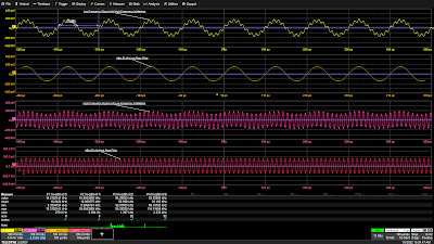
Figure 1: A 50 kHz low-pass filter eliminates a 93 kHz interfering signal from a 10 kHz signal (top two grids) and a 50 kHz high-pass filter cleans up a 93 kHz signal with an additive 10 kHz interfering signal (bottom two grids). Click image to expand.
Figure 1: A 50 kHz low-pass filter eliminates a
93 kHz interfering signal from a 10 kHz signal (top two grids)
and a 50 kHz high-pass filter cleans up a 93 kHz signal
with an additive 10 kHz interfering signal (bottom two grids).
Click image to expand.
In Pt. 1, we discussed the fundamental cause of unstable waveform displays. In this post, we’ll discuss how to use signal conditioners and conditional triggering to help the oscilloscope ignore extraneous samples when determining where the acquisition trigger event actually occurs.

Coupling 

In the Setup section of the Trigger dialog, Trigger input sources can be conditioned using AC or DC coupling, high-pass filters (LFREJ for low-frequency reject) and low-pass filters (HFREJ for high-frequency reject). The frequency selective coupling paths are used to attenuate extraneous signals. The low-frequency reject inserts a 50 kHz high-pass filter in the trigger signal path, which is useful for eliminating low-frequency interference such as 60 Hz power mains signals. This low-frequency noise can cause erroneous triggers, resulting in an unstable display. The high-frequency reject inserts a 50 kHz low-pass filter. This coupling mode finds use in applications such as troubleshooting switch-mode power supplies, where it suppresses signals at the power supply switching frequency. Like any extraneous signal, high frequency pickup can leak into the input signal and cause trigger instability. Figure 1 provides examples of how the HFREJ and LFREJ coupling filters eliminate interfering signals from the trigger source.

01 November 2018

How Equalization Works in 10x Passive Probes

The adjustable equalization circuit on the oscilloscope end of the coaxial cable compensates for the 10x passive probe's inherent low-pass filter characteristics
Figure 1: The adjustable equalization circuit on the oscilloscope
end of the coaxial cable compensates for the 10x passive
probe's inherent low-pass filter characteristics
We've been discussing 10x passive probes and their inner workings; our last post covered all the ways in which a 10x passive probe is apt to be a liability. They'd be basically unusable for any measurements at all but for one attribute: their equalization circuit (Figure 1). Without it, the 10x passive probe makes a pretty good low-pass filter, but the equalization circuit counters that with a high-pass filter to balance things out.

24 October 2018

Secrets of the 10x Passive Probe

The 10x passive probe  becomes a better measurement tool when we understand its limitations
Figure 1: The 10x passive probe
becomes a better measurement
tool when we understand its
limitations
We began this series of posts on oscilloscope probes by putting them in perspective: Probes have a number of different jobs to do, including serving effectively as both a mechanical and electrical interface. Despite having electrical attributes of their own, we want them to grab our signal of interest, but we don't want them to affect that signal in any way.

30 December 2014

Filtering Signals with MATLAB

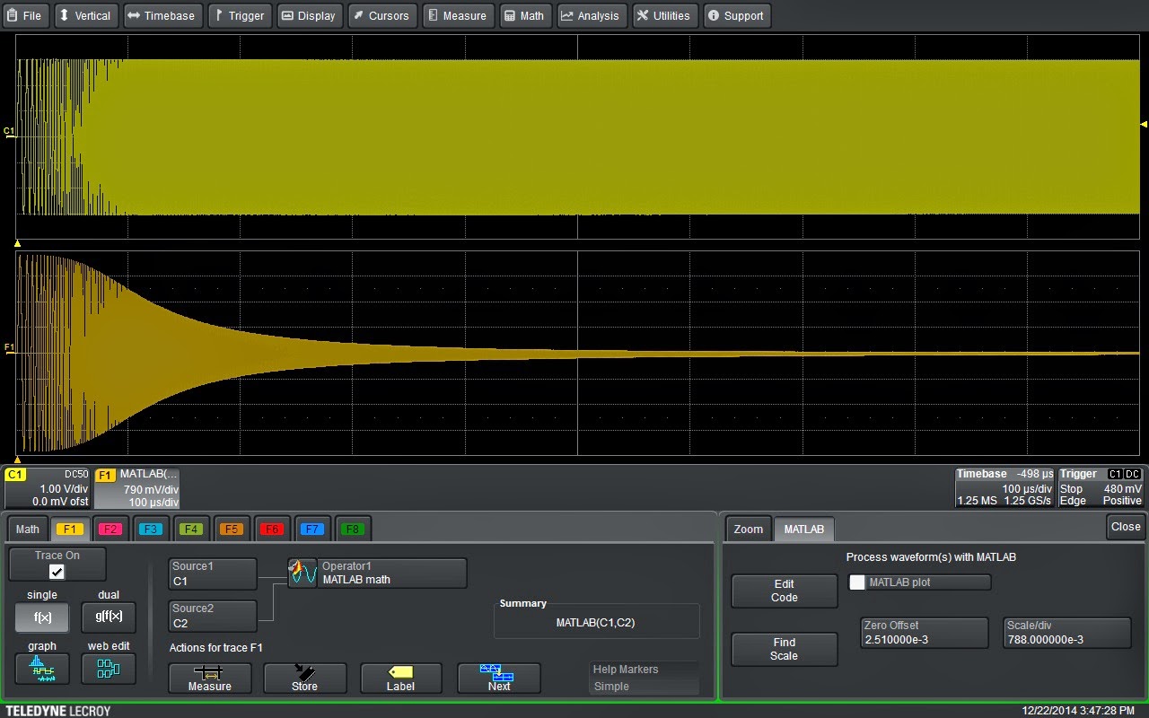
A 2-pole, 1-MHz Butterworth low-pass filter applied to an acquired waveform
Figure 1: A 2-pole, 1-MHz Butterworth low-pass filter
applied to an acquired waveform
Touted by its maker as "the language of technical computing," The MathWorks' MATLAB is a veritable Swiss Army knife for engineers, scientists, and perhaps anyone involved in technical endeavors. MATLAB serves a myriad of applications in programming, data analysis, application development, modeling and simulation, and... wait for it... instrument control!