You need to test, we're here to help.

You need to test, we're here to help.

27 April 2020

PCIe Electrical Testing: Where Are We?

PCIe specifications through Rev 5.0
Figure 1. PCIe specifications through Rev 5.0.


You may be wondering where we are in the roll out of PCI Express test specifications and active testing. Figure 1 shows the status as of March, 2020.

16 April 2020

Six Ways Not to be Confused by S-parameters (Part II)

In Part I, we discussed three causes of confusion when working with S-parameters and what you can do to avoid them.  In this post, we’ll discuss three more ways not to be confused by S-parameters.

4. Know the difference between return loss and reflection coefficient

Figure 1. A 2-port device has two distinctly interesting
S-parameters, S11 and S21.  S11 is the reflection
coefficient of Port 1 (also called return loss), and
S21 is the transmission coefficient of Port 2
(also called insertion loss).
Let’s start by looking at a 2-port device illustrated in Figure 1.

There are two S-parameters of interest in a 2-port device.  The first is the reflection coefficient, S11, that measures the ratio of the reflection from Port 1 to the drive signal at that port.  The second is the transmission coefficient, S21, that is the ratio of the output of Port 2 to the drive signal into Port 1.  Confusion arises because historical measurements of return loss and insertion loss are often used interchangeably with reflection coefficient and transmission coefficient, respectively.

13 April 2020

Six Ways Not to be Confused by S-parameters (Part I)


S-parameters describe the electrical properties of electronic interconnects, which can include connectors, printed circuit traces and vias, cables, and oscilloscope probes. Given that instruments such as Teledyne LeCroy’s WavePulser 40iX make measuring S-parameters relatively simple, there are still some aspects of S-parameters that can cause confusion, especially to new users. Here are six things you can do to avoid confusion when working with S-parameters.

1. Know where the fixture ends and the DUT begins
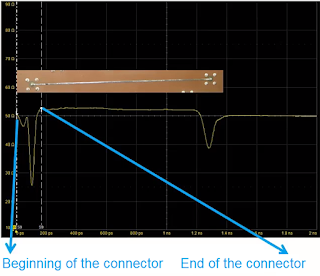
Connectors needed to make a measurement add their own characteristics to the measurement.
Figure 1. Characterizing a  microstrip line requires
two connectors, one at each end of the line. 
These connectors add their own characteristics to
the measurement. A TDR measurement can
determine the boundary between the connectors
and the microstrip PC line. 
Measuring S-parameters involves connecting a test instrument to the Device Under Test (DUT), placing the DUT in series with a number of other interconnect elements, as in Figure 1. The DUT is not isolated, and confusion can arise as to where you want the cables and fixtures to end and where the DUT begins. Do you want the DUT to include just the cable of the DUT? What about the connectors on its ends? What about the matching fixture or lead in in the circuit board?