
We've routinely posted on how you can characterize your total measurement system to gain important "situational awareness" when using an oscilloscope to make sensitive measurements. The knowledge gained from these tests helps you properly interpret your measurement results so that you can deduce what is actually going on with your circuit, versus what is an artifact of the measurement system. Listed here are nine important things you should know before making sensitive measurements with your oscilloscope, with links to blog posts that instruct you how to test them.
Showing posts with label Thevenin source voltage. Show all posts
Showing posts with label Thevenin source voltage. Show all posts
21 February 2022
07 February 2022
Transmission Lines for Oscilloscope Users, Part 3
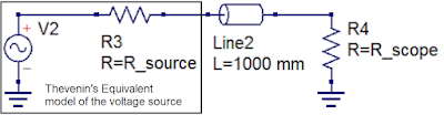 |
| Figure 1: The Thevenin equivalent circuit model can be used to characterize a voltage source with respect to the interconnect cable and oscilloscope input termination. |
Two terms needed for us to characterize the source are the Thevenin source voltage and the Thevenin source resistance. Once we know these, we have all the pieces we need to fully understand what is happening with our measurements. This is true whether the signal source is a Cal terminal or a device-under-test.

01 March 2018
Transmission Lines (Part V): Reverse-Engineering the DUT
 |
| Figure 1: Every DUT can be thought of as a Thevenin voltage source with some internal resistance |
Subscribe to:
Posts (Atom)