You need to test, we're here to help.

You need to test, we're here to help.

31 August 2020

Fundamentals of Power Integrity: Characterizing PDN Noise

Figure 1. Noise tolerances for embedded system
components are becoming ever tighter.
Power integrity concerns maintaining the quality of power from generation to consumption in an embedded system. “Good” power integrity could be defined as having noise levels that are within tolerance. This short series will focus on characterizing noise on your power delivery network (PDN), with the goal of knowing where you must adjust your design to meet those tolerances.

Why do we care about voltage rail noise? As electronic designs strive for ever lower power consumption, power rails already carry very low voltages, often 1 V or less. Components like RF receivers, ADCs and DACs can be affected by noise of less than 1% of the rail value (Figure 1). This means noise tolerances can be as tight as single-digit millivolts, which is why power integrity takes up considerable validation time in labs.

24 August 2020

How to Connect the Returns to an Unshielded Twisted Pair

Figure 1. Three options for connecting a TDR to a UTP.
During a recent webinar, Dr. Eric Bogatin was asked several questions about how to measure unshielded twisted pairs (UTPs), which are differential pairs with no return path. Here is his answer to one of the questions. For more information, check out the whole webinar on Differential Pairs with No Return Paths.

Q: For the UTP measurement, do you need to connect the SMA connector shield grounds together?

A: Yes. It’s very important to make sure the grounds are connected at the cable connectors.

There are really three ways the connections can be made from a differential TDR to the UTP cable. These three options are shown clockwise from left to right in Figure 1.

03 August 2020

How to Choose Between the Oscilloscope's 50 Ohm Input and 1 MOhm Input

Dr. Eric Bogatin

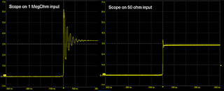
Fast buffered signal over a 1 megaohm input, and same signal over 50 ohm input
Figure 1. The same signal from a fast-buffer driver
measured with a 1-meter, 50 ohm cable with
1 megaohm input to the scope, and
same cable with 50 ohm input to the scope.
When every oscilloscope has both a 50 Ohm input and a 1 MOhm input, how do you choose which one to use? Here are my recommendations for when each input should be used. 

For additional information on this topic, check out my webinar on What Every Oscilloscope User Needs to Know About Transmission Lines.