You need to test, we're here to help.

You need to test, we're here to help.
Showing posts with label 10X attenuating probe. Show all posts

03 August 2020

How to Choose Between the Oscilloscope's 50 Ohm Input and 1 MOhm Input

Dr. Eric Bogatin

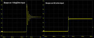
Fast buffered signal over a 1 megaohm input, and same signal over 50 ohm input
Figure 1. The same signal from a fast-buffer driver
measured with a 1-meter, 50 ohm cable with
1 megaohm input to the scope, and
same cable with 50 ohm input to the scope.
When every oscilloscope has both a 50 Ohm input and a 1 MOhm input, how do you choose which one to use? Here are my recommendations for when each input should be used. 

For additional information on this topic, check out my webinar on What Every Oscilloscope User Needs to Know About Transmission Lines.  

19 December 2018

Using 50-Ohm Coax From DUT to Oscilloscope

A coaxial cable presents high impedance at low frequencies but acts as a transmission line at higher frequencies
Figure 1: A coaxial cable presents high impedance at low
frequencies but acts as a transmission line at higher frequencies
In our recent exploration of 10x passive probes, we've determined that while these types of probes are great general-purpose tools, they're not necessarily going to do the job in specialized measurement circumstances. They're relatively low-bandwidth, low-SNR probes that impose some limitations and, in some scenarios, can deliver potentially misleading or erroneous measurement results if used without clear understanding of their capabilities.

12 December 2018

Squeezing More Bandwidth From a 10x Passive Probe

Shown is a comparison of inherent oscilloscope noise and noise at the shorted tip of a 10x passive probe
Figure 1: Shown is a comparison of inherent oscilloscope
noise and noise at the shorted tip of a 10x passive probe
Now that we have a better understanding of what's happening under the hood of a 10x passive oscilloscope probe, we can sum up its key characteristics. The first thing to know about such probes is that they offer relatively low bandwidth (<100 MHz). This is largely a result of the probe's tip inductance.

28 November 2018

10x Passive Probes and Cable Reflections

Figure 1: With unequal impedances at either end of the coax, are cable reflections a concern in 10x passive probes?
Figure 1: With unequal impedances at either end of the coax,
are cable reflections a concern in 10x passive probes?
We've been discussing the ubiquitous 10x passive probe here on Test Happens, beginning with an overview of the probe-oscilloscope system. We turned to the 10x passive probe itself and the issues posed by its constitutive circuitry. Then we covered what about that circuitry makes it usable at all, namely, its built-in equalization circuit.

08 November 2018

How Tip Inductance Impacts a Probing System's Bandwidth

Shown are FFT plots of a 10-MHz, fast-edge square wave reaching the oscilloscope via direct coax connection  (orange-yellow plot) and 10x passive probe fitted with a coax tip adapter (straw-colored plot)
Figure 1: Shown are FFT plots of a 10-MHz, fast-edge square
wave reaching the oscilloscope via direct coax connection
(orange-yellow plot) and 10x passive probe fitted with a coax
tip adapter (straw-colored plot)
If you're using 10x passive probes with your oscilloscope, it's important to understand the bandwidth of your probing system and how it's affected by various methods of probing the signal of interest. There's a relatively easy way to determine this parameter by probing a fast-edge, 10-MHz signal from a square-wave generator. Doing so can also instruct us in the effects of tip inductance on the probe's bandwidth.

01 November 2018

How Equalization Works in 10x Passive Probes

The adjustable equalization circuit on the oscilloscope end of the coaxial cable compensates for the 10x passive probe's inherent low-pass filter characteristics
Figure 1: The adjustable equalization circuit on the oscilloscope
end of the coaxial cable compensates for the 10x passive
probe's inherent low-pass filter characteristics
We've been discussing 10x passive probes and their inner workings; our last post covered all the ways in which a 10x passive probe is apt to be a liability. They'd be basically unusable for any measurements at all but for one attribute: their equalization circuit (Figure 1). Without it, the 10x passive probe makes a pretty good low-pass filter, but the equalization circuit counters that with a high-pass filter to balance things out.

24 October 2018

Secrets of the 10x Passive Probe

The 10x passive probe  becomes a better measurement tool when we understand its limitations
Figure 1: The 10x passive probe
becomes a better measurement
tool when we understand its
limitations
We began this series of posts on oscilloscope probes by putting them in perspective: Probes have a number of different jobs to do, including serving effectively as both a mechanical and electrical interface. Despite having electrical attributes of their own, we want them to grab our signal of interest, but we don't want them to affect that signal in any way.

19 January 2018

Bandwidth vs. Current Load in Power-Rail Measurements

Connecting a 6" length of coaxial cable between a low-impedance DUT and a 1-MΩ produces ringing artifacts on your signal acquisition
Figure 1: Connecting a 6" length of coaxial cable between
a low-impedance power rail and a 1-MΩ input impedance
produces reflections and ringing artifacts
on your signal acquisition
Among the various challenges we've discussed in measuring noise on power rails are RF pickup and signal-to-noise ratio (SNR). Here's another: how do you achieve high bandwidth in your measurements while also minimizing current load on your DUT? Given that your DUT is a power rail, you really don't want to draw too much current from it. But these two measurement criteria are at loggerheads with each other. It's a quandary, and it has to do with the fundamental nature of signals on interconnects.

18 January 2018

How 10X Attenuating Probes Kill Signal-to-Noise Ratio

Figure 1: Signal waveforms captured using a 10X attenuating
probe (top) and a BNC probe (bottom) with tips open
We've begun discussing things that can derail (see what we did there?) your power-rail measurements, such as the deleterious effects of RF interference. In the same context, one should always be mindful of certain characteristics of oscilloscope probes; namely, the 10X attenuating probes that are often lying around on the testbench.