You need to test, we're here to help.

You need to test, we're here to help.

15 March 2018

An Example of Three-Phase Power Measurements

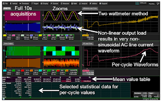
Screen capture of a 10-s acquisition of AC input and PWM output of a 480-V motor drive
Figure 1: Screen capture of a 10-s acquisition of AC input
and PWM output of a 480-V motor drive
To follow up on our last post on three-phase power calculations, and to wrap up this series of posts on the fundamentals of power, we'll walk through an example of a set of three-phase power measurements. We'll base our discussion on a single screen capture of measurements taken on a 480-V motor drive with 480-V AC input and 480-V maximum drive output. For this example, we used a Teledyne LeCroy Motor Drive Analyzer.

14 March 2018

Three-Phase Power Calculations

Three-phase power calculations entail summing of the individual phases's power calculations
Figure 1: Three-phase power calculations
entail summing of the individual
phases's power calculations
Until now, our discussions of power calculations have encompassed only single-phase systems with one voltage and one current. Now we'll turn to three-phase systems, which can be thought of as a collection of three single-phase systems. In general, three-phase power calculations are a simple summing of the individual phase power calculations and should be balanced across all three phases.

13 March 2018

Power Calculations for Distorted Waveforms

The sum of many sine waves, of varying amplitudes and frequencies, comprises the rough- looking square wave shown in red
Figure 1: The sum of many sine waves, of varying
amplitudes and frequencies, comprises the rough-
looking square wave shown in red
Our last post covered basic power calculations for pure sine waves, which are useful only up to a point in that pure sine waves are rather rare in the real world. Almost any real-world waveform carries some amount of distortion. Because distorted voltage and current waveforms comprise multiple frequencies, the relatively simple techniques used to measure power for pure, single-frequency sine waves no longer apply.

09 March 2018

Power Calculations for Pure Sine Waves

 For a purely resistive load, power = voltage * current, with both vectors in phase
Figure 1: For a purely resistive load,
power = voltage * current, with both vectors in phase
Wouldn't it be wonderful if every sine wave we encountered in the real world was pure, with no distortion? It sure would make life easier. Alas, it's pretty much never the case. But in reviewing sinusoidal power calculations, it's best that we begin with the simplest case: a single, pure sinusoidal line voltage and single, pure sinusoidal line current supplying a linear load.

Back to Basics: AC Sinusoidal Line Current

A single-phase AC current vector rotates at 50 or 60 Hz
Figure 1: A single-phase AC current
vector rotates at 50 or 60 Hz
We've reviewed the basics of AC line voltage in previous posts. Now we'll turn our attention to the other fundamental component of line power. Regardless of whether you call it "grid," "household," "line," "utility," or "mains," AC sinusoidal current is what flows from the power utility's lines into every home and business.

02 March 2018

More Basics of Three-Phase AC Sinusoidal Voltages

In the Wye three-phase connection, neutral is present but sometimes inaccessible
Figure 1: In the Wye three-phase
connection, neutral is present but
sometimes inaccessible
Our last post in this series on the essential principles of power covered the basics of three-phase voltages: their composition of three voltage vectors, how they're generated, how they're measured (line-line or line-neutral), and conversion of line-line values to line-neutral values. Here, we'll pick up the thread with more on three-phase AC voltages.

01 March 2018

Transmission Lines (Part V): Reverse-Engineering the DUT

Every DUT can be thought of as a Thevenin voltage source with some internal resistance
Figure 1: Every DUT can be thought of as a Thevenin
voltage source with some internal resistance
There are always two primary elements of any test and/or measurement application: the oscilloscope and the device under test (DUT). Getting valid measurement results depends, first and foremost, on the oscilloscope's capabilities given the task at hand. It also depends on what we'll call "situational awareness," or the operator's understanding of the oscilloscope and of the characteristics of the DUT.