You need to test, we're here to help.

You need to test, we're here to help.
Showing posts with label compliance test. Show all posts

04 January 2021

Decision Feedback Equalization in DDR

Figure 1. A transmitted rectangular pulse suffers distortion by the time it reaches the receiver.  Broadening and reflections from previous transmitted bits add to the pulse response,  creating inter-symbol interference.
Figure 1. A transmitted rectangular pulse suffers
distortion by the time it reaches the receiver. 
Broadening and reflections from previous
transmitted bits add to the pulse response, 
creating inter-symbol interference.

High-speed serial links such as those used in DDR4 and DDR5 are subject to a variety of signal degradation challenges.  Insertion losses, frequency dependent attenuation and inter-symbol interference (ISI), as well as others, are among the most commonly encountered sources of signal degradation. 

Figure 1 shows how reflections can cause ISI on a rectangular pulse. When a rectangular pulse is transmitted, it suffers distortion which is apparent when it reaches the receiver.  It may be broadened due to group delay dispersion because different frequency components of the signal propagate along the signal path at differing velocities. In addition, there may be echo pulses, due to impedance mismatches in the channel.  These mismatches cause reflections that propagate back and forth over the channel and appear as these echoes where subsequent bits should be.

14 December 2020

Removing Reflections from DDR Signals Probed Mid-Bus

Figure 1. Virtual probing methods like VP@Rcvr can help remove reflections from signals probed mid-bus.
Figure 1. Virtual probing methods like VP@Rcvr can help
remove reflections from signals probed mid-bus.
Probing DDR signals can present some interesting challenges. The JEDEC specification indicates that all measurements should be made at the output pins of the memory chip. The challenge comes because sometimes the pins of the memory chip are not accessible. You may be able to use an interposer, but even that requires some spatial displacement from the probing point to the Ball Grid Array (BGA) pins of the memory chip. 

If the board has already been populated, there is an even greater problem because the interposer can’t be used, so probes may have to be placed in the middle of the bus in order to make a measurement. In this situation, the probe picks up signals reflected from the memory controller and the memory chip, as well as the desired signals. Reflections appear as non-monotonic ripples on the edges of DQ and DQS signals, as shown in Figure 2.

07 December 2020

Isolating DDR Read and Write Operations

Figure 1. DDR DQ and DQS signals are in phase during a Read operation and out of phase during a Write operation.
Figure 1. DDR DQ and DQS signals are
in phase during a Read operation and
out of phase during a Write operation.
Whether you are debugging or running compliance tests on Double Data Rate (DDR) or Low Power Double Data Rate (LPDDR) memory, the analysis process requires the separation of Read and Write operations to enable measurements on each distinct operational mode. 

The phase relationship between the Data (DQ) signal and the Data Strobe (DQS) signal indicates the type of operation, as shown in Figure 1.

The DQ and DQS signals are phase aligned with edges overlapping in Read mode. In Write mode, they are out of phase, and the DQS edge overlaps the center of the DQ eye.  In the lower speed versions of DDR memory devices, the measuring instrument could be triggered on this phase difference, enabling the isolation of the desired operation for testing.

01 June 2020

USB4 Electrical Testing: Where Are We?

Preliminary drafts of the USB4 Compliance Test Specifications (CTS) were released to USB-IF work group members in early 2020 covering the electrical through protocol layer testing of USB4 router assemblies captive cable devices. These CTS documents define the required testing for USB4 hosts, hubs, and peripherals that make up the USB4 ecosystem.  Thunderbolt 3 (TBT3) is also supported in USB4 end products and is tested using the existing TBT3 Host/Device CTS.

While the electrical test methodologies are similar to previous USB 3.2 compliance tests, USB4 is largely based off the TBT3 physical layer, and these test methods have been adopted. Here, we summarize the USB4/TBT3 test approach called out in the aforementioned documents.

USB4 Transmitter Testing

Figure 1. Test points TP2 and TP3 for USB4 Electrical Compliance Testing (Source: USB-IF)
Figure 1. Test points TP2 and TP3 for USB4
Electrical Compliance Testing (Source: USB-IF)
Presently, there is no SIG-TEST software for performing transmitter (Tx) testing, although it is anticipated that one will be released by the USB-IF in the future. All Tx tests performed by QPHY-USB4-TX-RX utilize Teledyne LeCroy methods, with measurements made directly by the oscilloscope.

Figure 1 shows the Test points defined in the CTS for physical layer testing. Testing of the Tx-side is  similar to those performed for USB 3.2 in that the signal is captured at the connector (TP2), where many measurements are defined. Then, a passive cable model is embedded and equalization is applied to result in TP3 measurements.

27 April 2020

PCIe Electrical Testing: Where Are We?

PCIe specifications through Rev 5.0
Figure 1. PCIe specifications through Rev 5.0.


You may be wondering where we are in the roll out of PCI Express test specifications and active testing. Figure 1 shows the status as of March, 2020.

10 May 2018

Debugging Ethernet, SATA, and PCIe for IoT Devices

A generic IoT block diagram shows serial-data links in blue
Figure 1: A generic IoT block diagram
shows serial-data links in blue
In our ongoing review of debugging serial-data standards for Internet of Things (IoT) devices, let's now turn to three more popular protocols: Ethernet, SATA, and PCIe. Ethernet is found in computer networking applications, while the Serial Advanced Technology Attachment (SATA) connects host bus adapters to mass-storage devices. The Peripheral Component Interconnect Express (PCI Express or PCIe) handles communication between root complexes (motherboards) and expansion-card interfaces.

16 January 2018

PCIe 4.0 PLL Bandwidth Testing

PLL bandwidth testing ensures that the add-in card's PLL bandwidth and peaking are within specifications
Figure 1: PLL bandwidth testing
ensures that the add-in card's
PLL bandwidth and peaking
are within specifications
The final piece of the PCIe 4.0 compliance-test puzzle—at least until PCI-SIG completes its test definitions—is the PLL bandwidth test. This test, which is performed only on add-in cards, verifies that the PLL bandwidth and peaking are within the limits allowed by the PCIe 4.0 specification (Figure 1).

15 January 2018

PCIe 4.0 Receiver Link-Equalization Testing (Part II)

Working out the optimal combination of Tx emphasis presets and receiver CTLE settings
Figure 1: Working out the optimal combination of Tx emphasis
presets and receiver CTLE settings
As may be apparent from our previous post on PCIe 4.0 receiver link-equalization testing, this part of the PCIe 4.0 compliance tests is somewhat involved. When we left off last time, we were in the midst of receiver calibration, looking to ensure that the test-signal eye is as closed as possible without violating the specification limits.

PCIe 4.0 Receiver Link-Equalization Testing (Part I)

PCIe 4.0 receiver link-equalization testing takes place at the site of the channel's worst-case signal
Figure 1: PCIe 4.0 receiver link-equalization testing
takes place at the site of the channel's worst-case signal
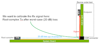
In the battery of PCIe 4.0 compliance tests, there is but a single test of receiver behavior: Rx link-equalization testing. Given that our DUT in this test is an add-in card, we want to have our worst-case signal at the Card ElectroMechanical (CEM) connector (Figure 1). The signal then proceeds through the channel on the add-in card to the end point, which is the receiver on the DUT.

PCIe 4.0 Transmitter Link-Equalization Testing

Shown is an overview of the PCIe 4.0 link-equalization response test
Figure 1: Shown is an overview of the PCIe 4.0
link-equalization response test
PCI Express has seen steady, and significant, increases in bit rates in each generational revision. Most recently, bit rates leaped from 8 Gb/s in PCIe 3.0 to 16 Gb/s in the current version 4.0. With these speed increases has come the need for dynamic link equalization, which becomes necessary for the sake of signal integrity. Compliance tests for dynamic link equalization is where things start to get a little more sophisticated, particularly when it comes to PCIe 4.0

12 January 2018

PCIe 4.0 Transmitter Electrical Testing (Part II)

With an add-in card as our DUT, we will measure the transmit signal at the root complex on the system board
Figure 1: With an add-in card as our DUT, we will measure
the transmit signal at the root complex on the system board
With PCIe 4.0 compliance workshops close at hand, let's get familiar with the compliance test process. We've set the stage for electrical transmitter tests by describing the PCIe 4.0 nominal channel and also reviewed the test-equipment requirements; now we'll begin examining the tests in some detail. The two basic transmitter tests are the preset test and signal-quality test.

PCIe 4.0 Transmitter Electrical Testing (Part I)

The two basic PCIe 4.0 transmitter tests outlined in green
Figure 1: The two basic PCIe 4.0 transmitter tests
are shown above outlined in green
You've been introduced to some of the background and history that has brought the PCI Express protocol standard to its fourth generation, and we've discussed the test-equipment requirements for PCIe 4.0 electrical compliance testing. Let's begin examining the compliance testing, beginning with transmitter electrical tests.

11 January 2018

Introduction to PCIe 4.0 Electrical Compliance Test

PCIe logo
Figure 1: PCI Express is now in its fourth generation
and poses daunting physical-layer test challenges
The Peripheral Component Interface Express standard (PCI Express, or PCIe) has been with us for some 14 years now, a pretty good run by computer-industry standards, and it shows no signs of fading away anytime soon. Now in its fourth generation, which sports data-transfer rates up to 16 Gb/s, PCIe presents daunting physical-layer test requirements (Figure 1).

12 October 2017

Automotive Ethernet Compliance: Tests in Detail (Part III)

This depicts the setup for the Automotive Ethernet transmitter distortion test
Figure 1: This depicts the setup for the Automotive
Ethernet transmitter distortion test
Among the compliance tests specified for Automotive Ethernet in the 100Base-T1 spec, none is more complex to set up than the test for transmitter distortion. As with the transmitter timing slave jitter test described in an earlier post, it requires access to the DUT's transmit clock (TX_TCLK).

08 September 2017

Automotive Ethernet Compliance: Test Setup Overview

Typical test setup for Automotive Ethernet PMA compliance test
Figure 1: Typical test setup for Automotive Ethernet
PMA compliance test
Our last post, an overview of the five test modes for Automotive Ethernet electrical compliance testing, prepared us for a deeper look at the compliance tests themselves. But before diving into details on the differential electrical compliance tests for Automotive Ethernet, be it BroadR-Reach or 100Base-T1, it might be helpful to take a look at the setup for this endeavor.

24 August 2017

Introduction to Automotive Ethernet Compliance Testing

As with most any networking scheme, Automotive Ethernet is subject to standardization to ensure that the various components of a given system reliably pass signals among themselves. Where there is a standard for a protocol, there must also be testing for compliance with that standard. This will be the first in a series of posts detailing compliance test of the Physical Media Attachment (PMA) aspect of the Automotive Ethernet standard.

27 July 2017

The Periodic Table of Oscilloscope Tools: Document

Teledyne LeCroy's Document toolset for its oscilloscopes
Oscilloscope users can find themselves managing a lot of detail in the course of driving their instruments. They need to keep track of instrument setups. They have to know standards-based compliance test routines backward and forward. Often, the need arises to remotely control the oscilloscope, interface it with other applications, and export/import acquisition data. And, importantly, the oscilloscope has to aid, and not hinder, collaboration with other members of the engineering team(s).

And thus we arrive at the end of our survey of the Periodic Table of Oscilloscope Tools with the Document portion.
  • Hardcopy: Use the oscilloscope's Print button to pre-define a documentation action and execute that action with the press of one button. Select to create a file of a screen image in a variety of formats; send an email with an attached screen image; copy data to a clipboard; print a document; or save the waveform data, screen images, panel setups, and the end user's annotations as a LabNotebook (see below).

29 June 2017

Distinguishing BroadR-Reach and 100Base-T1

BroadR-Reach provides full-duplex operation over a single twisted pair of wires
Figure 1: BroadR-Reach provides full-duplex operation
over a single twisted pair of wires
The world of Automotive Ethernet can be a little confusing in that there are two dominant specifications that serve the application space: BroadR-Reach and 100Base-T1. Both are explicitly intended for automotive use and there's quite a bit of overlap between them. In this installment, we'll look a little more closely at BroadR-Reach applications and also explain the differences between it and 100Base-T1.

27 June 2017

The Basics of Automotive Ethernet Testing

Automotive Ethernet PHY test requires 1-GHz bandwidth and 2-GS/s sample rate minimum
Figure 1: Automotive Ethernet
PHY test requires 1-GHz bandwidth
and 2-GS/s sample rate minimum
Now that we've discussed what Automotive Ethernet is all about, discussed its benefits, and dug deeper into BroadR-Reach, the next topic for discussion is an overview of testing for the protocol and the equipment requirements to test the physical layer.

30 May 2017

An Inside Look at an Automotive Ethernet Seminar

Students gain first-hand experience in Automotive Ethernet protocol testing
Figure 1: Students gain first-hand experience in
Automotive Ethernet protocol testing
Teledyne LeCroy's Automotive Technology Center (ATC) in Farmington Hills, MI recently hosted a full-day seminar on Automotive Ethernet. Below, Bob Mart, product line manager, shares some of his thoughts on how the seminar went and provides a preview of Teledyne LeCroy's next live Automotive Ethernet day at the ATC on June 15, 2017 (detailed information on this and other automotive-related events can be found here).