You need to test, we're here to help.

You need to test, we're here to help.
Showing posts with label bandwidth. Show all posts

21 February 2022

9 Important Things to Know When Making Sensitive Measurements with Oscilloscopes

We've routinely posted on how you can characterize your total measurement system to gain important "situational awareness" when using an oscilloscope to make sensitive measurements. The knowledge gained from these tests helps you properly interpret your measurement results so that you can deduce what is actually going on with your circuit, versus what is an artifact of the measurement system. Listed here are nine important things you should know before making sensitive measurements with your oscilloscope, with links to blog posts that instruct you how to test them.

18 January 2021

Situational Awareness: Testing Oscilloscope Outer Limits

Fig 1. 40 ps signal measured full bandwidth on a 1 GHz oscilloscope shows visible over/undershoot.
Fig 1. 40 ps signal measured full bandwidth on a
1 GHz oscilloscope shows visible over/undershoot.
Nothing is perfect. Every test instrument has its limits, and knowing the limits to your oscilloscope’s bandwidth in response to real-world signals helps to develop situational awareness when making measurements. This is especially true when testing signals that are at or very near the specified bandwidth limit of the instrument.

The measurements we’ll demonstrate were made on a WaveSurfer 4104HD, a 12-bit, 4-channel, 1 GHz bandwidth oscilloscope that samples at up to 5 GS/s.

19 December 2018

Using 50-Ohm Coax From DUT to Oscilloscope

A coaxial cable presents high impedance at low frequencies but acts as a transmission line at higher frequencies
Figure 1: A coaxial cable presents high impedance at low
frequencies but acts as a transmission line at higher frequencies
In our recent exploration of 10x passive probes, we've determined that while these types of probes are great general-purpose tools, they're not necessarily going to do the job in specialized measurement circumstances. They're relatively low-bandwidth, low-SNR probes that impose some limitations and, in some scenarios, can deliver potentially misleading or erroneous measurement results if used without clear understanding of their capabilities.

12 December 2018

Squeezing More Bandwidth From a 10x Passive Probe

Shown is a comparison of inherent oscilloscope noise and noise at the shorted tip of a 10x passive probe
Figure 1: Shown is a comparison of inherent oscilloscope
noise and noise at the shorted tip of a 10x passive probe
Now that we have a better understanding of what's happening under the hood of a 10x passive oscilloscope probe, we can sum up its key characteristics. The first thing to know about such probes is that they offer relatively low bandwidth (<100 MHz). This is largely a result of the probe's tip inductance.

08 November 2018

How Tip Inductance Impacts a Probing System's Bandwidth

Shown are FFT plots of a 10-MHz, fast-edge square wave reaching the oscilloscope via direct coax connection  (orange-yellow plot) and 10x passive probe fitted with a coax tip adapter (straw-colored plot)
Figure 1: Shown are FFT plots of a 10-MHz, fast-edge square
wave reaching the oscilloscope via direct coax connection
(orange-yellow plot) and 10x passive probe fitted with a coax
tip adapter (straw-colored plot)
If you're using 10x passive probes with your oscilloscope, it's important to understand the bandwidth of your probing system and how it's affected by various methods of probing the signal of interest. There's a relatively easy way to determine this parameter by probing a fast-edge, 10-MHz signal from a square-wave generator. Doing so can also instruct us in the effects of tip inductance on the probe's bandwidth.

23 February 2018

Transmission Lines (Part II): More on Bandwidth vs. Rise Time

In the frequency domain (right), a near-ideal square wave displays predictable 1/f amplitude dropoff
Figure 1: In the frequency domain (right), a near-ideal
square wave displays predictable 1/f amplitude dropoff
We began this series about transmission lines by thinking about some pertinent principles and relationships that can help form our thinking about the topic. In particular, we'd covered the relationship between bandwidth and rise time and why we have this rule of thumb that says that bandwidth can be estimated using 0.35/10-90% rise time.

20 February 2018

Transmission Lines (Part I): Introduction

All oscilloscopes have a Cal output like the one pictured here
Figure 1: All oscilloscopes
have a Cal output like the
one pictured here
Somewhere on the front panel of almost any oscilloscope is a "Cal" reference signal output (Figure 1). That signal is really intended for adjusting the capacitance compensation screw to calibrate a 10X high-impedance probe, but most of us know it simply as the Cal signal. Have you ever noticed that the Cal signal's rise time seems to be highly dependent on the length of the cable attached to it, and maybe even wondered why?

26 January 2018

Getting The Most Out Of Your Oscilloscope: Setup

Choosing a effective sample rate is key to seeing the finer details of a waveform
Figure 1: Choosing a effective sample rate is key
to seeing the finer details of a waveform
Today's real-time digital oscilloscopes are so packed with bells and whistles (or "features," if you prefer) that you can forget how to use many of them. In fact, you might not even realize some exist! But they're all there for a reason, and they're all useful, maybe even more so than you know. To that end, we'll take a tour of a typical Teledyne LeCroy oscilloscope's features and give you some pointers as to how, and when, you can best take advantage of them.

06 December 2017

Probing Techniques and Tradeoffs (Part IV)

Applying bandwidth filters to a 2.5-GHz clock signal clearly shows the effect of bandwidth on rise time
Figure 1: Applying bandwidth filters to a 2.5-GHz clock
signal clearly shows the effect of bandwidth on rise time
The topic of probe bandwidth is a broad and deep one. We began our discussion of bandwidth in an earlier post with some basic information about what bandwidth means and the importance of the -3 dB point. Next, we looked at a Fourier deconstruction of a square wave into its fundamental and the lower-order harmonics, and covered the importance of bandwidth in capturing enough harmonic content to understand the signal's overall shape.

27 November 2017

Probing Techniques and Tradeoffs (Part III)

Bandwidth is defined as the frequency at which the ratio of the displayed amplitude to the input amplitude is -3 dB (or 0.707)
Figure 1: Bandwidth is defined as the frequency at which
the ratio of the displayed amplitude to the input amplitude
is -3 dB (or 0.707)
Any discussion of oscilloscopes and/or probes must include the topic of analog bandwidth. Bandwidth is one of a short list of key specifications for a testbench setup. All oscilloscopes and probes come to market with a bandwidth specification, which is defined as:

The frequency at which the ratio of the displayed amplitude to the input amplitude is -3 dB (or 0.707).

This is known as the "-3 dB point," or the half-power point (Figure 1). At this frequency, a sine-wave input signal is attenuated to 70.7% of its true amplitude. Any higher frequencies will likely be distorted on the display, making accurate measurements and calibration impossible.

20 November 2017

Probing Techniques and Tradeoffs (Part II)

A snapshot of available probes from Teledyne LeCroy
Figure 1: A snapshot of available probes from
Teledyne LeCroy
Our first post in this series concentrated on connectivity and various means by which one might apply an oscilloscope probe to a circuit or device under test. Now, we'll look at an "ideal" probe vs. a real-world probe, and then begin a discussion of probe specifications.

19 May 2017

Testing the DDR Memory Interface's Physical Layer (Part IV)

Probes are a key element of the total signal acquisition system
Figure 1: Probes are a key element of the total signal
acquisition system
In this multipart survey of testing the DDR interface's physical layer, we've looked at the basics of the interface itself, a high-level overview of the testing, how to access DDR signals, and read/write burst separation. In this installment, we'll cover preparation for the actual testing.

04 March 2016

Performance Considerations For Optical Modulation Analysis

Error-vector magnitude defined
Figure 1: Error-vector magnitude defined
In recent posts, we've covered the fundamentals of coherent signals and the basics of optical modulation analyzers. Let's now turn to the operational parameters of OMAs, in particular system bandwidth, and how that figure of merit in an OMA can determine how far your measurement system can take you in terms of meaningful analysis.

06 August 2015

Why High Oscilloscope Sampling Rates Matter

Figure 1: Here is an example of aliasing that results from sampling a signal at less than the Nyquist rate of 2fmax
Figure 1: Here is an example of aliasing that results from
sampling a signal at less than the Nyquist rate of 2fmax
A key to accurate measurements with an oscilloscope is to ensure that the instrument maintains a high sampling rate. This applies to most measurements; conversely, for many measurements, accuracy may suffer as sample rate decreases. In the worst case, some signal components may be "aliased," meaning that the true signal shape is corrupted by the addition of bogus signal components that arise from undersampling of real signal components.

27 March 2015

Oscilloscope Basics: Choosing an Oscilloscope
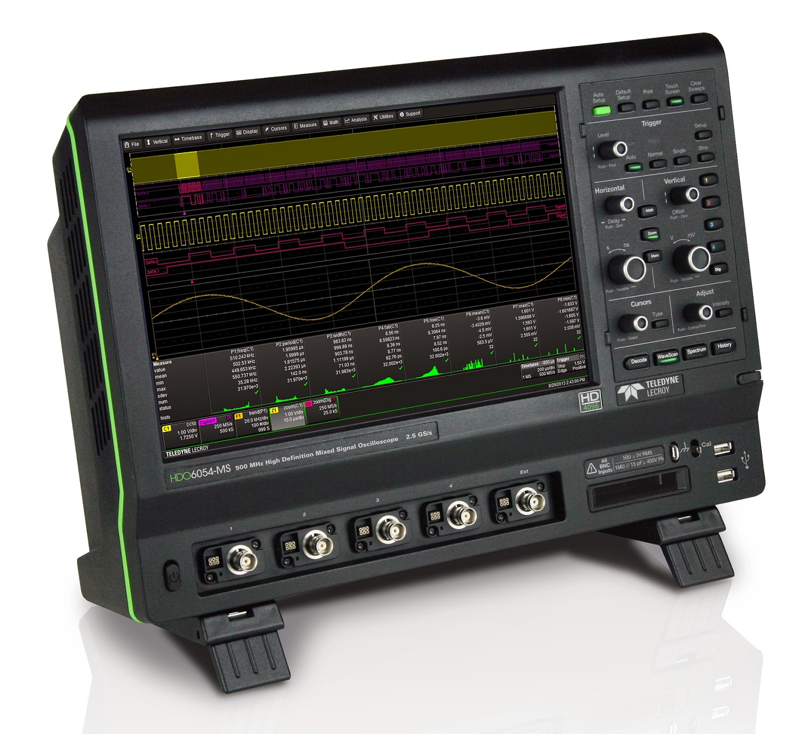
An oscilloscope such as Teledyne LeCroy's HDO6054-MS serves a very broad range of applications
Figure 1: An oscilloscope such as
Teledyne LeCroy's HDO6054-MS
serves a very broad range of
applications
Choosing an oscilloscope might seem to be a challenging task, but it doesn't have to be. Rather, it's a more-or-less logical process based on your measurement needs. Having said that, if the application for the instrument is "general lab work," the decision can become trickier.

10 June 2013

Oscilloscope Basics: Sampling Rate

In a recent overview post on oscilloscope banner specifications,
one of the topics covered is sampling rate. Let's do a somewhat deeper dive on that topic and look at what sampling rate means to oscilloscope users.

29 May 2013

An Overview of Oscilloscope Banner Specs

"Banner specs" is a term that oscilloscope makers use often. If you've ever met with one of the vendors' salespeople, you're likely to have heard it. But what are banner specs and what do they mean to you?

05 April 2013

The Making of 12-Bit Scope Hardware

In many applications, the accuracy of a true 12-bit oscilloscope is not only desirable, but necessary. Going forward, this will become the case more and more often. When choosing one, it's a good idea to peek under the covers and gain a little insight into how the instrument operates. Having discussed in an earlier post the advantages of oscilloscopes with 12-bit vertical resolution, let's look at the ways in which that resolution is accomplished in hardware.

01 April 2013

Oscilloscope Basics: Oscilloscope Bandwidth

Among the most important basic specifications of a digital oscilloscope is its bandwidth. Knowing a bit about bandwidth and the influences on the specification can be very helpful in selecting the right oscilloscope for your application. This post will cover some fundamental aspects of oscilloscope bandwidth.