You need to test, we're here to help.

You need to test, we're here to help.
Showing posts with label rise-time degradation. Show all posts

07 February 2022

Transmission Lines for Oscilloscope Users, Part 3

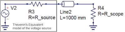
Figure 1: The Thevenin equivalent circuit model can be used to characterize a voltage source with respect to the  interconnect cable and oscilloscope input termination.
Figure 1: The Thevenin equivalent circuit model can be used
to characterize a voltage source with respect to the 
interconnect cable and oscilloscope input termination.
In Part 2, we demonstrated how to calculate the instantaneous impedance of a transmission line. However, any measurement made using an oscilloscope should consider not only the transmission line, but the source, the transmission line and the oscilloscope as a system. Therefore, characterizing your source, as well as knowing the effects of your oscilloscope input impedance, is important to developing the “situational awareness” needed to interpret measurements properly.

Two terms needed for us to characterize the source are the Thevenin source voltage and the Thevenin source resistance. Once we know these, we have all the pieces we need to fully understand what is happening with our measurements. This is true whether the signal source is a Cal terminal or a device-under-test.

13 June 2018

Inter-Symbol Interference (or Leaky Bits)

Inter-symbol interference, or ISI jitter, is the result of information from one bit "leaking" to subsequent bits
Figure 1: Inter-symbol interference, or ISI jitter, is the result
of information from one bit "leaking" to subsequent bits
In reviewing the subject of debugging high-speed serial links, one important aspect of signal integrity we must touch on is inter-symbol interference (ISI). ISI is the phenomenon in which information from one bit "leaks" to some subsequent number of bits.