You need to test, we're here to help.

You need to test, we're here to help.
Showing posts with label impedance matching. Show all posts

14 February 2022

Transmission Lines for Oscilloscope Users, Part 4

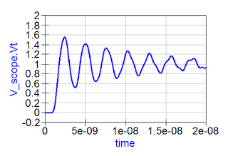
Figure 1: Characteristic waveform when the source impedance is lower than the cable impedance.
Figure 1: Characteristic waveform when the source
impedance is lower than the cable impedance.
In Part 3, we saw the pattern of reflections that occur when both the source impedance and the oscilloscope input impedance are higher than that of the interconnect, and how those reflections affected the rise time measurement. Now let’s briefly consider what happens when the source impedance is lower than the impedance of the connecting cable. 

For this example, the source voltage is a 3.3 V square wave and the source impedance is 9 Ω. As before, our transmission line is a 50 Ω coaxial cable connecting the source to the oscilloscope. If the oscilloscope input termination is set to 1 MΩ, we see the interesting waveform shown in Figure 1.

13 September 2018

Decision Feedback Equalization

DFE filter output is based on a linear combination of previous bit decisions
Figure 1: DFE filter output is based on
a linear combination of previous bit
decisions
In debugging high-speed serial links, one must be cognizant of various forms of equalization that might be used in the link to compensate for signal degradation in the channel. Inter-symbol interference (ISI), attenuation, impedance mismatches, and insertion losses can all contribute to this loss of signal quality. To combat these effects, designers implement techniques such as continuous time linear equalization and feed-forward equalization.

10 July 2018

Serial-Data Channel Emulation and S Parameters

Higher data rates + "same old" channel media = degraded signal quality at receiver
Figure 1: Higher data rates + "same old" channel media
= degraded signal quality at receiver
Serial data rates have risen but propagation media for the channel remain unchanged, and that results in greater attenuation to the frequencies of interest. We could ignore these losses at lower frequencies, but now that rise times are so much faster, that's not an option. Channel effects now intrude into design margins to the point where eyes deteriorate and bit-error rates become unacceptable.

06 June 2018

A Look at Transmission-Line Losses

Using a 3D field solver to simulate a differential trace
Figure 1: Using a 3D
field solver to simulate
a differential trace
In surveying the subject of debugging high-speed serial data links, we've noted that there's no one cause for signal-integrity issues between transmitter and receiver, and there's certainly no one solution. But let's begin with the low-hanging fruit: electrical losses in the transmission line. We've previously done a series of posts on transmission lines (beginning here), but it's worth it to have a quick refresher.

05 June 2018

Introduction to Debugging High-Speed Serial Links

These images depict the degradation of serial data traffic as it makes its way from transmitter to receiver
Figure 1: These images depict the degradation of serial data
traffic as it makes its way from transmitter to receiver
In recent years, the data rates in serial links have increased exponentially across any number of standard protocols, including PCI Express, USB, and even SATA and SAS. With higher data rates comes more challenges for system designers, validation engineers, and test engineers with respect to signal integrity (SI). Some SI effects are much more prominent at higher data rates than they were for lower-speed versions of the same protocols. In this series of posts, we'll examine these SI effects, look at some methods of improving system performance, and discuss some SI analysis solutions as well as measurement considerations.

15 May 2018

Debugging DDR Memory on IoT Devices

Embedded systems such as IoT devices often require chip interposers to gain access to signal lines on DDR memory
Figure 1: Embedded systems such as IoT devices often require
chip interposers to gain access to signal lines on DDR memory
Internet of Things (IoT) devices are, at heart, just another embedded computing system, albeit one with an extremely well-defined function. As such, there's bound to be some amount of on-board data storage, and the storage medium of choice these days is typically double data-rate (DDR) memory. DDR memory transfers serial data on both the rising and falling edges of the clock signal, which is the characteristic from which it derives its name.

19 January 2018

Bandwidth vs. Current Load in Power-Rail Measurements

Connecting a 6" length of coaxial cable between a low-impedance DUT and a 1-MΩ produces ringing artifacts on your signal acquisition
Figure 1: Connecting a 6" length of coaxial cable between
a low-impedance power rail and a 1-MΩ input impedance
produces reflections and ringing artifacts
on your signal acquisition
Among the various challenges we've discussed in measuring noise on power rails are RF pickup and signal-to-noise ratio (SNR). Here's another: how do you achieve high bandwidth in your measurements while also minimizing current load on your DUT? Given that your DUT is a power rail, you really don't want to draw too much current from it. But these two measurement criteria are at loggerheads with each other. It's a quandary, and it has to do with the fundamental nature of signals on interconnects.