
The USB Type-C® connector is designed to be very simple for the user to use: you insert it in either orientation, and a multitude of services just “work”. Though simple to use, it is a complicated connector to program and test, with a very complex system of protocols behind it. There is USB power delivery (USB-PD) and multiple rates of USB data delivery from USB 2.0 through USB4®, specified by the USB Implementers Forum (USB-IF®). There are protocols other than USB, such as DisplayPort™, High-Definition Multimedia Interface (HDMI™), Peripheral Component Interconnect Express (PCIe®), Base-T Ethernet and Thunderbolt™.
So, what actually happens when you connect a USB-C cable? To understand that, first let’s take a look at the signals and pin assignments in the USB-C connector receptacle (Figure 1).
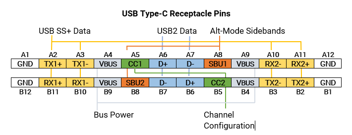 |
Figure 1: The USB-C receptacle pin assignments showing the key signals used for device-to-device communications. Related pins have matching color overlays. |


