 |
Figure 1: The typical manner
of using a hands-free probe
holder can cause issues |
Having covered many of the theoretical aspects of probing signals, it's now useful to cover some best practices for high-speed active probing. We'll use some examples involving probing of DDR memory to illustrate what works best and what might not be a good idea from a practical standpoint.
For starters, you can't probe a circuit effectively without making good, clean contact with it. To that end, there are some important issues that can make or break DDR (or any) probing.
 |
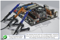
Figure 2: Use probe holders in a
reverse-mount fashion for better
signal fidelity |
The hands-free probe holder is a must in many and diverse probing applications. However, how you use it can make or break (literally) your probe's connection with a DDR circuit. When used in typical fashion, the hands-free holder is intended to place the probe-and-holder's weight at the probe tip (Figure 1). But this can result in instability at the point of contact that might break or weaken the solder joint.
 |
Figure 3: A gooseneck strain relief
helps ensure that solder-in probe tips
stay securely attached |
A better approach to using the hands-free holder is to deploy it in reverse fashion (Figure 2). Doing so provides a counterweight, balancing the probe so as not to have it apply pressure to the connection. By removing force from the probe tip, you gain some strain relief on the connection, avoiding solder-joint issues and ensuring good signal fidelity into the probe.
Yet another recommended technique for high-speed signals such as DDR memory is to use a gooseneck strain-relief device (Figure 3). The idea is to mount the adhesive base of the gooseneck device onto an adjacent chip package, bend it toward the point of contact, and solder the tip of the probe it's holding to the circuit.
 |
Figure 4: Careless probe placement as
shown here will result in crosstalk |
Probe placement is an important consideration. Figure 4 depicts probes soldered to DDR DQ and DQS signals. Note the juxtaposition of the probe that's picking up the clock signal to that which is probing the data line; in this configuration, there is some crosstalk between the clock and data signals. The best configuration is to have the data-signal connection at about 90° from the clock-signal connection, which will avoid the crosstalk pollution of the data line from the clock.
We'll resume descriptions of some best practices for probing in an upcoming post.
Previous posts in this series:
Probing Techniques and Tradeoffs (Part I)
Probing Techniques and Tradeoffs (Part II)
Probing Techniques and Tradeoffs (Part III)
Probing Techniques and Tradeoffs (Part IV)
Probing Techniques and Tradeoffs (Part V): Probe Loading
Probing Techniques and Tradeoffs (Part VI): Dynamic Range
Probing Techniques and Tradeoffs (Part VII): More on Dynamic Range
Probing Techniques and Tradeoffs (Part VIII): Gain/Attenuation vs. Noise


No comments:
Post a Comment