You need to test, we're here to help.

You need to test, we're here to help.
Showing posts with label S-matrix. Show all posts

17 May 2021

Converting Single to Mixed-Mode S-Parameters

Figure 1: Model of two transmission lines with crosstalk showing the transmission and crosstalk related S-parameters.
Figure 1: Model of two transmission lines with crosstalk
showing the transmission and crosstalk related S-parameters.

We have introduced mixed mode S-parameters and developed a formal structure for handling them. It is now time to discuss converting single-ended S-parameters into mixed-mode S-parameters. This is important because every instrument manufacturer obtains mixed mode S-parameters by first measuring single-ended S-parameters, then converting them mathematically to mixed-mode. This assumes that the interconnects being measured are passive, linear and time invariant.  Let’s begin with our model of two transmission lines with crosstalk shown in Figure 1.

10 July 2018

Serial-Data Channel Emulation and S Parameters

Higher data rates + "same old" channel media = degraded signal quality at receiver
Figure 1: Higher data rates + "same old" channel media
= degraded signal quality at receiver
Serial data rates have risen but propagation media for the channel remain unchanged, and that results in greater attenuation to the frequencies of interest. We could ignore these losses at lower frequencies, but now that rise times are so much faster, that's not an option. Channel effects now intrude into design margins to the point where eyes deteriorate and bit-error rates become unacceptable.

17 December 2014

What S-parameters Reveal About Interconnects (Part III)

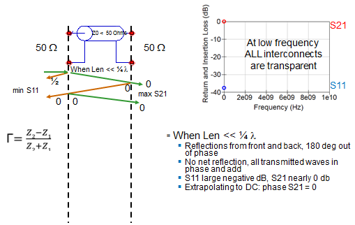
How ripple is introduced into S11 and S21
Figure 1: How ripple is introduced into S11 and S21
S-parameters are a great tool for understanding exactly what happens to a signal as it traverses an interconnect such as a transmission line. How much of it propagates through, and how much reflects off of impedance mismatches? From plotting return loss against insertion loss, we've weighed how much return loss may be tolerable before it significantly impacts insertion loss. Now we'll turn our attention to some common patterns exhibited by S11 and S21 and what they mean to the performance of an interconnect.

09 December 2014

What S-parameters Reveal About Interconnects (Part II)

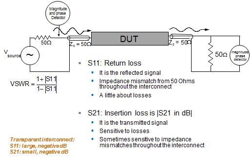
Measuring S-parameters of a two-port interconnect
Figure 1: Measuring S-parameters
of a two-port interconnect
Having previously covered some of the fundamentals of S-parameters, it's now time to dig a little deeper into what they can show us about an interconnect; say, for example, a two-port microstrip line on a PC board. Unlike the one-port DUT in our earlier post, this configuration gives us the opportunity to look at not only S11 (return loss or reflected signal), but also S21 (insertion loss or transmitted signal).

03 December 2014

What S-Parameters Reveal About Interconnects

S-parameters are derived by applying an incident wave to an interconnect
Figure 1: S-parameters are derived by applying an incident
wave to an interconnect; we can consider this process in either
the time or frequency domains
S-parameters are a popular means of characterizing an interconnect. By feeding the interconnect with a precision reference signal and measuring how much of that signal propagates through the connector and how much is reflected, we learn everything we need to know about its performance. This will be the first in a series of posts about the insights we can glean from S-parameters with practical examples of common measurement scenarios.

15 May 2014

Back to Basics: S-parameters

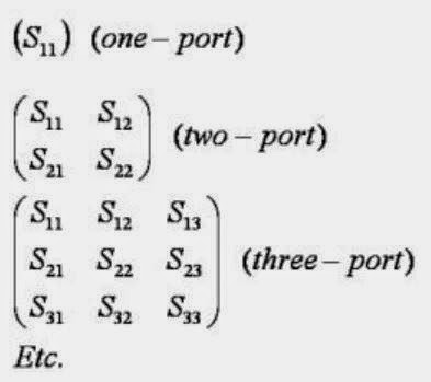
S-matrices for one-, two-, and three-port RF networks
Figure 1: S-matrices for one-, two-,
and three-port RF networks
Suppose you have an optical lens of some sort onto which you shine a light with a known photonic output. While most of the incident light passes through the lens, some fraction of the light is reflected and some is absorbed (the behavior is also dependent on the wavelength of the incident light). You'd like to characterize that lens: Exactly how much light was reflected? How much passed through? What is it about the lens that prevented all of the light from passing through?