You need to test, we're here to help.

You need to test, we're here to help.

28 November 2022

New 60 V Offset Power Rail Probes Offer the Capability Needed for 48 V Power Integrity Analysis

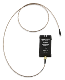
RP4060 Rail Probe
Figure 1. The RP2060 and RP4060
build on the legacy of the RP4030 power
rail probe. The new probes are ideally
suited to working with the new 48 Vdc 
power structures.
In 2016, Teledyne LeCroy first offered the RP4030 Power Rail Probe, which was designed to enable engineers to probe a low-impedance, low-voltage DC power/voltage rail signal without loading the device under test (DUT). It provided ±30 V of probe offset to allow a DC power/voltage rail signal to be displayed in the vertical center of the oscilloscope regardless of the gain (sensitivity) setting.

Recently, we released two, new power rail probes that build on those capabilities—the 2 GHz RP2060 and 4 GHz RP4060. Both probes feature:

  • ±60 V Offset Capability
  • ±800 mV Dynamic Range
  • 50 kΩ DC Input Impedance (for low loading of low-impedance power rails)
  • 1.2:1Attenuation (for low additive noise)
  • MCX-terminated cable with a variety of board connections: 4 GHz*-rated MCX PCB mount;
    4 GHz* solder-in; 3 GHz* coaxial cable to U.FL PCB mount; optional 500 MHz browser
* Bandwidths listed are for the 4 GHz RP4060. Maximum bandwidth when used with RP2060 is 2 GHz.

Why the New Probes?

One driver of the new release is the increase in the number and size of data centers needed to support cloud computing and other data-intensive applications, and the new power architectures they require. The new rail probe is designed to ideally meet the needs of engineers working with power rails rated up to 48 Vdc.

21 November 2022

Oscilloscope Serial Data Measurements and DAC: Trigger, Decode, Measure/Graph and Eye Diagram Software

Table of serial bus measurement parameters
Figure 1. Serial bus measurements made available
with "TDME" and "TDMP "decoder options.
All Teledyne LeCroy oscilloscopes support a rich set of standard waveform measurement parameters, but the installation of any "TDME" or "TDMP" serial decoder software option adds special parameters designed for measuring serial data buses. Besides automating the measurement of serial bus timing, these parameters allow you to access encoded serial data and extract it to analog values for what is essentially a Digital-to-Analog Converter (DAC)!

What’s in a Name?

Teledyne LeCroy has adopted the convention of using a key in the name of our serial trigger and decode products that tells you what capabilities they offer.  The “ME” or “MP” in the name of a Teledyne LeCroy serial decoder option (e.g., CAN FDbus TDME or USB4-SB TDMP) refers to "Measure/Graph and Eye Diagram" or "Measure/Graph and Physical Layer Tests." All these options include the following 10 serial bus measurements. Physical Layer Test options will also include measurements designed specifically to meet the requirements of the standard.

14 November 2022

SDAIII and QualiPHY Software: Oscilloscope Eye Diagrams for Compliance and Debug

Figure 1. SDAIII enables eye diagrams and eye
measurements of four lanes of  streaming data.
Besides the serial TDME and TDMP options discussed earlier, there are other ways to generate eye diagrams on your Teledyne LeCroy oscilloscope for compliance testing and debug.

SDAIII Serial Data Analysis Software

SDAIII offers the most comprehensive eye diagram capabilities for Teledyne LeCroy oscilloscopes, with tools for optimizing the displayed eye that are especially useful to high-speed serial data analysis.

11 November 2022

Serial Trigger, Decode, Measure/Graph & Eye Diagram (TDME) Software: Oscilloscope Eye Diagrams for Debug

Eye diagrams generated from two serial decodes.
Figure 1. Two eye diagrams generated from 
three active USB serial decoders.
Click any image to enlarge it.

The eye diagram is a general-purpose tool for analyzing the signal integrity of serial digital communications signals. It shows the effects of additive vertical noise, horizontal jitter, duty cycle distortion, inter-symbol interference, and crosstalk on a serial data stream. The vertical opening of the eye is affected by these elements, as well as gain differences between devices on the bus, so that the more problems with signal integrity, the more “sleepy” the eye appears. A wide open eye is indicative of good signal integrity.

It is commonplace to use an oscilloscope with decoder software to analyze the health of serial data streams, where the combination of the electrical waveform and the link layer decoding shows if and where the protocol breaks down at the physical layer, but an eye diagram can better show the degree of signal interference that may be impacting the serial logic—especially if it could be generated for particular devices or packets.