You need to test, we're here to help.

You need to test, we're here to help.
Showing posts with label pulse-width modulation. Show all posts

21 September 2020

Fundamentals of Power Integrity: Board Pollution

Figure 1. "Pollution" occurring on PDN traces.
Board pollution is noise occurring on the packages and interconnects (traces and planes) that carry current from the VRMs to the consumer devices.
One place it can originate is from the VRM itself, for example, with the switching noise the VRM generates (Figure 1). That can be a real concern if the board capacitance means you have a resonance around the switching frequency that would act as an amplifier for the switching noise and cause all kinds of problems with other devices on the board.

14 September 2020

Fundamentals of Power Integrity: Self-aggression Noise

Fig. 1: VRM-switching noise is a self aggressor that can be identified because it is synchronous with the PWM clock.
Fig. 1: VRM-switching noise is a self aggressor that can be
identified because it is synchronous 
with the PWM clock. 
Self-aggression noise is so-called because it is inflicted by a component onto itself through its normal operation; nothing else in the system is affecting it. When we look for this, we want to ensure the system is in a steady state, in a place where the noise environment is fairly clear (e.g., the device is on an evaluation board).

An example of self-aggression would be VRM-switching noise. Figure 1 shows ripple on a 900 millivolt rail (yellow trace) at a time when no load is present. One of the things that tells us this is switching noise is that it is synchronous to the PWM clock (red trace). Ripple that is synchronous with the switching clock is a typical figure of merit for identifying switching noise.

19 April 2018

IoT Digital Power Management and Power Integrity

The half-bridge output current from each DC-DC phase is known as the inductor current
Figure 1: The half-bridge output
current from each DC-DC phase
is known as the inductor current
An Internet of Things (IoT) device derives its power either from a 12-V DC supply or from a battery. In either case, power is fed to one or more power rails that operate at different voltages. These rails power the CPU and other functional blocks on the PC board. In this post, we'll take a look at how to examine an IoT's power supply for proper digital power management implementation and for power integrity.

21 October 2015

Analyzing Pulse-Width Modulation Signals

Persistence display provides a quick-and-dirty view of a PWM signal
Figure 1: Persistence display provides
a quick-and-dirty view of a PWM signal
Pulse-width modulation (PWM), a favorite technique for achieving analog ends through digital means, finds application in all kinds of end systems. Motor control might be the number-one application, but PWM turns up in telecommunications, audio systems and amplifiers, and any number of other uses. Armed with a capable oscilloscope, one can thoroughly analyze and understand the behavior of PWM circuits.

05 June 2015

Testing Challenges in Motor Drive Systems (Part III)

Figure 1: An example of PWM for a single power semiconductor
Figure 1: An example of PWM for
a single power semiconductor
As noted in an earlier post, variable-frequency motor drives (VFDs) display a good amount of variation in terms of architectures and topologies. Another differentiator between VFDs is their application of pulse-width modulation (PWM) techniques.

15 April 2015

Testing Challenges in Motor Drive Systems (Part II)

Yhe complete design and debug challenge posed by a variable-frequency motor drive
Figure 1: This image depicts the complete design and
debug challenge posed by a variable-frequency motor drive
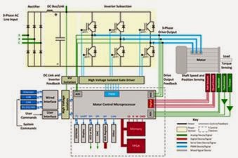
In our first post on motor drive systems, we broke down the major subsystems in a "generic" variable frequency drive (VFD) and discussed some of the test requirements in those subsystems (Figure 1). Next, let's have a look at some of the variations in real-world VFDs in terms of architectures and topologies.

07 April 2015

Testing Challenges in Motor Drive Systems

The power section of a motor drive system requires measurements of line input, PWM output, and efficiencies
Figure 1: The power section of a motor drive system requires
measurements of line input, PWM output, and efficiencies
Motors are everywhere in our world, and nowhere more so than in  our vehicles. For example, when's the last time you had to crank a car window up and down to pay a highway toll? Or, for that matter, when did you last manually adjust the seat position or rear-view mirror angles? These aspects of vehicles are all typically motorized these days.

09 October 2013

Waveform Generator Tricks: Pulse-Width Modulation

Teledyne LeCroy's WaveStation waveform generator
Figure 1: Teledyne LeCroy's WaveStation
waveform generator
Imagine that you're designing a digital control circuit but you really want it to behave like an analog circuit. Say, something like light dimmers, or a motor controller. A tried-and-true approach is to use pulse-width modulation (PWM) to have your digital control logic emulate the behavior of analog control. And your handy-dandy waveform generator, if so equipped, is a great way to generate a PWM signal to test out your design.