You need to test, we're here to help.

You need to test, we're here to help.
Showing posts with label triggering. Show all posts

13 June 2022

Oscilloscope Basics: Cal Out and Aux Out

Figure 5. New PCIe 6.0 compliance pattern signal.
Fig. 1: Cal Out and Aux Out 
provide many useful outputs.
Oscilloscopes are generally thought of in terms of the signals that are input to them, but even oscilloscopes that are not equipped with function/signal generators can usually output some useful test signals.

Nearly all oscilloscopes have a Cal Out (calibration output) terminal on the front. Most Teledyne LeCroy oscilloscopes also have an Aux Out (auxiliary output) connector on either the front or back, depending on  model. Both outputs provide configurable signals that can assist you to compensate probes and attenuators, test frequency response, trigger waveform acquisition and coordinate multiple test instruments.

04 January 2022

Oscilloscope Basics: Stabilizing Waveform Display, Pt. 1

Figure 1: A free running oscilloscope starts each acquisition at a different point on the waveform, resulting in an unstable display.  A triggered oscilloscope starts each acquisition at the same point on the waveform, resulting in a stable display.
Figure 1: A free running oscilloscope starts each
acquisition at a different point on the waveform,
resulting in an unstable display.  A triggered oscilloscope
starts each acquisition at the same point on the
waveform, resulting in a stable display. 
An unsynchronized, unstable oscilloscope display is useless for making measurements, but proper triggering can synchronize the oscilloscope sample clock to specific waveform events so that the acquired waveforms appear stable on the display.  Let’s look at why signals can appear unstable and what to do about it.  

Oscilloscopes are sampling devices; they sample the incoming signal at a uniform rate.  The timing of a signal applied to the input of an oscilloscope is most probably asynchronous with the oscilloscope’s sampling clock.  If the oscilloscope timebase is allowed to run free—that is, not synchronized to the timing of the input signal—then each oscilloscope acquisition potentially begins at a different point on the input waveform, as shown in Figure 1.

29 August 2018

A Walk-Through of Ground-Bounce Measurements

The trigger pulse from the MCU is one clock cycle in width
Figure 1: The trigger pulse from the
MCU is one clock cycle in width
In earlier posts in this series, we've explained what ground bounce is and how it happens. We have also taken a deeper dive into the use of I/O drivers to implement sense lines that let us better quantify and analyze what kind of ground-bounce hit our system is taking. Now, let's look at a detailed example of how to measure and diagnose ground bounce.

29 January 2018

Getting The Most Out Of Your Oscilloscope: Trigger Delay

Pre-triggering, or trigger delay, is a useful tool for debugging applications
Figure 1: Pre-triggering, or trigger delay, is a useful tool for
debugging applications
Triggering is one of the most basic, yet most useful, tools your oscilloscope offers you. Say you want to see what led up to, and/or what follows, a trigger condition. You're looking at an interesting waveform such as that shown in Figure 1. You have the trigger's delay position set at 10% and 90%.

11 September 2015

For UART Debugging, Triggering is Key

A typical screen capture of UART serial decode/trigger software
Figure 1: A typical screen capture of UART
serial decode/trigger software
In our survey of how modern oscilloscopes and trigger/decode software (Figure 1) can ease the task of debugging embedded systems, we've covered the I2C and SPI protocols. Now we'll turn to the UART format, where triggering capabilities are of particular importance.

27 March 2015

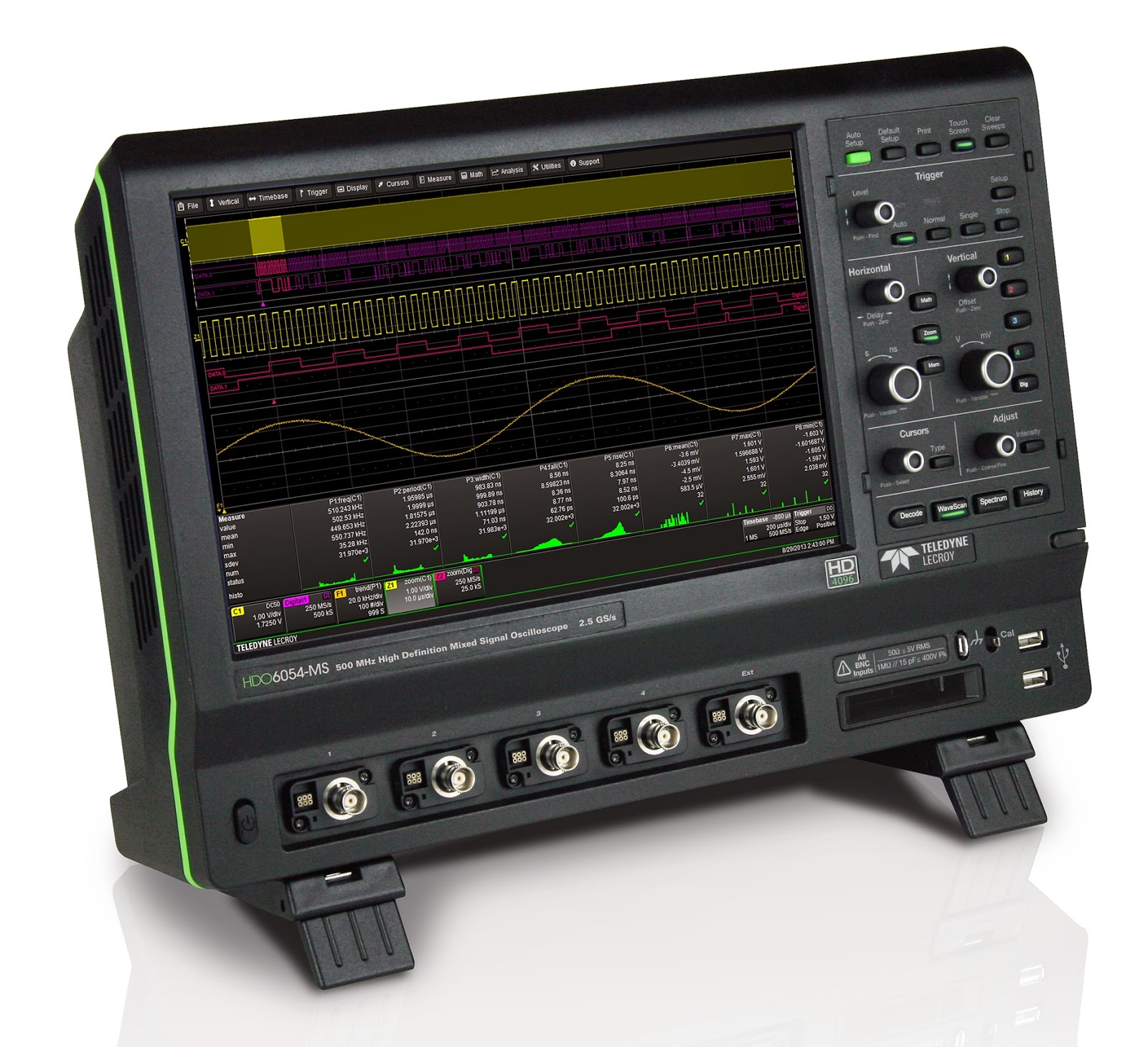
Oscilloscope Basics: Choosing an Oscilloscope

An oscilloscope such as Teledyne LeCroy's HDO6054-MS serves a very broad range of applications
Figure 1: An oscilloscope such as
Teledyne LeCroy's HDO6054-MS
serves a very broad range of
applications
Choosing an oscilloscope might seem to be a challenging task, but it doesn't have to be. Rather, it's a more-or-less logical process based on your measurement needs. Having said that, if the application for the instrument is "general lab work," the decision can become trickier.

29 January 2014

Tips and Tricks: Stabilizing a Waveform Trace

One initial challenge to oscilloscope users is achieving a stable display of an input waveform. In almost all cases, the Auto Setup button on Teledyne LeCroy oscilloscopes (and most other modern instruments) will automatically set the oscilloscope's triggering system to get that jumpy trace to settle down.

18 December 2013

Oscilloscope Basics: Trigger Holdoff

As discussed in an earlier post, triggering is the means by which we can coax an oscilloscope into showing us what we're looking for in an input signal, and indeed even simply to display it in a stable fashion. Two of the most basic triggering types are edge triggers and pattern triggers. The latter applies to mixed-signal instruments, allowing users to trigger on a logical combination of analog and digital inputs.

02 October 2013

Oscilloscope Basics: Controlling An Oscilloscope (Part I)

Front of HDO6054 oscilloscope
Figure 1: Front of HDO4054 oscilloscope
At first glance, the front of today's oscilloscopes can be daunting. For starters, there's an array of physical "hard" controls. Relatively recent models may also sport touch screen displays with so-called "soft" controls. For one thing, getting familiar with the front of these instruments is only a matter of experimentation and common sense. And for another, what at first may seem complex is carefully designed to make the instrument as easy to operate as possible. This is the first installment of a projected series of posts that will explain how to control a modern oscilloscope. Here, we'll start with the front panel.

26 June 2013

Back to Basics: Sequence Mode

Figure 1: Sequence mode enables fast trigger rates and optimizes memory usage by ignoring dead time.
Figure 1: Sequence mode enables fast trigger rates
and optimizes memory usage by
ignoring dead time.
Now and again, an oscilloscope user may need to capture either a large number of fast pulses in quick succession, or a small number of events separated by relatively long periods of time. Either of these scenarios are challenging with typical acquisition modes. Fortunately, most modern oscilloscopes offer what we call "sequence mode" (other oscilloscope makers refer to similar acquisition modes as "fast-frame" or "segmented memory" mode).

17 May 2013

Oscilloscope Basics: Triggering

At some point, it's likely you've had the experience of capturing a waveform on your oscilloscope only to see a wildly unstable trace displayed on the screen. Chances are that you hadn't adjusted the triggering correctly. Let's take a brief look at what triggering is and why it's important in an oscilloscope. Trigger modes determine when the oscilloscope acquires and what is displayed.