 |
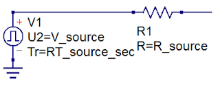
| Figure 1: Every DUT can be thought of as a Thevenin voltage source with some internal resistance |
On the oscilloscope side, you want to pay attention to the "banner specs," the key specifications that give the instrument its core capabilities. These include attributes such as:
- Sample rate
- Time base
- Number of samples in an acquisition
- Vertical resolution
- Analog bandwidth
- Intrinsic rise time
- Input impedance setting
You also should know some things about the probe and its cabling, such as its bandwidth, and its time delay. The typical RG-174 coaxial probe cable has a bandwidth of 3-4 GHz. The characteristic impedance is 50 Ω, and with a 3' length, the time delay is about 4.5 ns.
Then there's the DUT, and every device you examine is a Thevenin voltage source with some internal source resistance (Figure 1). When we do a measurement at the output of the DUT, what we measure depends on some figures of merit, namely the voltage, the resistance, and the rise time. Without being aware of these attributes of the DUT, it's going to be difficult to interpret the measurement results.
But what if you don't know these figures of merit? You can reverse-engineer your DUT to determine them.
Step 1 (Figure 2) is to measure the DUT's output with the oscilloscope set to a 1-MΩ input impedance. We won't be loading down the source, so if we give it enough time, the voltage we measure is the unloaded, open-circuit Thevenin source voltage, Vsource.
Step 2 is to measure the DUT voltage with the oscilloscope's input impedance to 50 Ω. Now, before you make the voltage measurement with this oscilloscope setting, make absolutely sure that the voltage you'll be measuring is less than 5 VRMS. The oscilloscope's front end is, in essence, a 50-Ω load that is rated for only about 0.5 W, and with more than 5 VRMS, you could be endangering the instrument. A good practice, especially if you don't know much about your input signal, is to first measure that unloaded voltage with a 1-MΩ input impedance to determine whether or not you should be using a higher-voltage probe.
With that caveat, we measure the DUT's output with the oscilloscope set at 50 Ω. What should we see? We would expect to see a voltage drop at Vout in Figure 1. That voltage drop will depend on the value of Rsource. We have created a voltage divider by measuring the voltage across 50 Ω, and we can calculate the measured voltage using:
Previous posts in this series:
Transmission Lines (Part I): Introduction
Transmission Lines (Part II): More on Bandwidth vs. Rise Time
Transmission Lines (Part III): Essential Principles
Then there's the DUT, and every device you examine is a Thevenin voltage source with some internal source resistance (Figure 1). When we do a measurement at the output of the DUT, what we measure depends on some figures of merit, namely the voltage, the resistance, and the rise time. Without being aware of these attributes of the DUT, it's going to be difficult to interpret the measurement results.
But what if you don't know these figures of merit? You can reverse-engineer your DUT to determine them.
Reverse-Engineering DUT Figures of Merit
Here's how to characterize any DUT and extract those figures of merit. Remember that a DUT has some Thevenin source voltage and source resistance as well as an intrinsic rise time. |
| Figure 2: This schematic depicts a DUT's Thevenin source voltage and resistance connected to an oscilloscope termination |
Step 1 (Figure 2) is to measure the DUT's output with the oscilloscope set to a 1-MΩ input impedance. We won't be loading down the source, so if we give it enough time, the voltage we measure is the unloaded, open-circuit Thevenin source voltage, Vsource.
Step 2 is to measure the DUT voltage with the oscilloscope's input impedance to 50 Ω. Now, before you make the voltage measurement with this oscilloscope setting, make absolutely sure that the voltage you'll be measuring is less than 5 VRMS. The oscilloscope's front end is, in essence, a 50-Ω load that is rated for only about 0.5 W, and with more than 5 VRMS, you could be endangering the instrument. A good practice, especially if you don't know much about your input signal, is to first measure that unloaded voltage with a 1-MΩ input impedance to determine whether or not you should be using a higher-voltage probe.
With that caveat, we measure the DUT's output with the oscilloscope set at 50 Ω. What should we see? We would expect to see a voltage drop at Vout in Figure 1. That voltage drop will depend on the value of Rsource. We have created a voltage divider by measuring the voltage across 50 Ω, and we can calculate the measured voltage using:
Now that we know Vmeas, and we'd already measured Vsource and know the value of Rscope, we can calculate Rsource using:
The next item on the agenda is to measure the DUT output signal's rise time, and we'll pick up with that in a subsequent post.
Previous posts in this series:
Transmission Lines (Part I): Introduction
Transmission Lines (Part II): More on Bandwidth vs. Rise Time
Transmission Lines (Part III): Essential Principles


1 comment:
Should I worry about loading a CMOS output with a DC 50 Ohm load?
Post a Comment