You need to test, we're here to help.

You need to test, we're here to help.
Showing posts with label DIMM. Show all posts

17 January 2022

9 Quick Fixes to Improve DDR Probing

Figure 1: Reversed Handsfree mounts and chip clips help relieve strain on fragile solders.
Figure 1: Reversed Handsfree mounts and chip
clips help relieve strain on fragile solders.
Probing at DRAM pins as required by JEDEC can be challenging. Here are nine, simple ways to improve your DDR probing.

1. Use positioning tools to relieve strain on probe tips

The Handsfree probe holder included as an accessory with several Teledyne LeCroy probes, such as the WaveLink and DH Series probes, was originally designed to put weight on the probe tip to ensure a good contact. However, many DDR probing applications utilize solder-in (SI) tips, where the greater concern is to relieve strain on the tip so as to not disrupt the solder. It turns out that if you use the Handsfree in a “reverse mounted” orientation (Figure 1), it puts the amplifier in a perfect position to help relieve strain on probe tips.

12 February 2018

Probing Techniques and Tradeoffs (Part X): More Best Practices

Chip clips; they're not just for snacks anymore
Figure 1: Chip clips;
they're not just for
snacks anymore
In probing circuits, as with most endeavors, there are some best practices you can use to enhance your chances of obtaining optimal measurements. We began exploring this concept in our last post, and we'll continue here with more best practices.

11 April 2017

Testing the DDR Memory Interface's Physical Layer (Part II)

A typical BGA package for DDR memory
Figure 1: Shown is a typical BGA
package for DDR memory
In the first of this series of posts, we undertook a high-level view of physical test of a DDR memory interface. Moving forward, let's look into some of the specific challenges one faces in a close examination of these interfaces.

08 October 2014

DDR Memory Testing Part III: What Not to Do

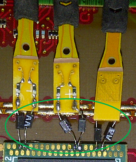
Damping resistors on solder-in probe tips  terminating at chip interposer
Figure 1: Damping resistors on
solder-in probe tips
Testing of dual data-rate memory (DDR) devices and/or modules calls for careful application of some best practices for probing. There will also be cases where the use of chip interposers is called for. Heeding the advice provided in earlier Test Happens posts on this topic will go a long way toward successful probing and testing.

01 October 2014

DDR Memory Testing Part II: Using Interposers

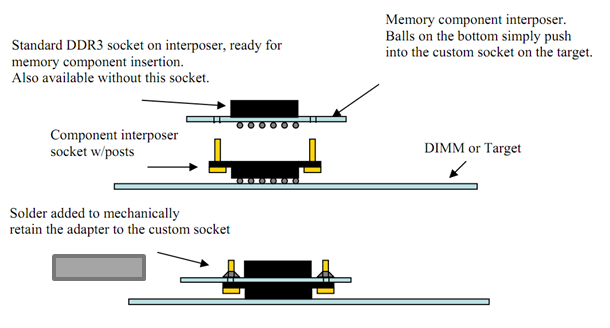
The anatomy of a chip interposer
Figure 1: The anatomy of a chip interposer
If you're a PCB layout designer, you've probably heard one or more test engineers complain: "Why can't you lay out the board so that it can be tested?" All too often, components that need to be accessible to oscilloscope probes are physically inaccessible, whether it's because of close proximity of adjacent components or ball grid array (BGA) mounting of the DUT. It's nearly always a necessary evil, though, because of PCB cost and/or mechanical constraints.