You need to test, we're here to help.

You need to test, we're here to help.

08 December 2016

Back to Basics: Fundamentals of AC Line Power (Part II)

AC line voltage is a single-phase vector that rotates at a given frequency
Figure 1: AC line voltage is a single-phase
vector that rotates at a given frequency
Having reviewed a broad definition of power, how it is generated and distributed, and how motors consume almost half of all generated power, we will now turn to a more detailed discussion of just what it is that we call "power." When we discuss "power," we're typically referring to what comes out of a wall socket: AC line, or sinusoidal, power.

18 November 2016

Back to Basics: The Fundamentals of Power


45% of worldwide power consumption fuels motors
Figure 1: 45% of worldwide power
consumption fuels motors
Ask any number of engineers to define "power" and you'll get any number of answers, and none of them would necessarily be wrong. Sometimes it's just a matter of perspective.

30 September 2016

Dynamic Range, Signal Integrity, and ESD Pulses

Use your oscilloscope's full vertical range to take full advantage of the ADC's resolution
Figure 1: Use your oscilloscope's full vertical range to
take full advantage of the ADC's resolution
Having considered the impact of sampling rate on ESD pulse measurements, let's now turn our attention to dynamic range and signal integrity. No matter what oscilloscope you use, it's important to make the most of the instrument's full vertical range to achieve maximum accuracy.

28 September 2016

How Does Sampling Rate Affect ESD Pulse Measurements?

Characterization of an ESD pulse's rise time depends largely on the oscilloscope's sampling rate
Figure 1: Characterization of an ESD pulse's rise time
depends largely on the oscilloscope's sampling rate
In continuing our look at ESD/EMC pulse measurements, it would be useful to consider how sampling rate figures into the equation. What sort of sampling rate makes sense to use for capturing an ESD pulse? The answer to that question depends primarily on your pulse's rise time.

13 September 2016

Why IEEE's Pulse Definitions and ESD Pulses Don't Mix
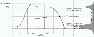
The IEEE's pulse definitions, which don't fit the bill for measuring ESD pulses
Figure 1: The IEEE's pulse definitions, which don't fit
the bill for measuring ESD pulses
The IEEE's pulse definitions, found in the organization's Std 181-2011 that covers transitions, pulses, and related waveforms, set the bar for how pulse measurements are determined. These definitions, which are in the DNA of all oscilloscopes, are just the thing for measuring repetitive pulses such as clock signals but not so much for ESD/EMC measurement requirements. In this post, we'll discuss why that is and what you should do differently for measuring ESD pulses.

30 August 2016

Making EMC/ESD Pulse Measurements

Four quadrants of EMC/ESD testing
Figure 1: Oscilloscopes are used for
testing in the green-shaded boxes
There are many circumstances in which electromagnetic compatibility (EMC) and electrostatic discharge (ESD) testing are a fact of life. Many countries have adopted IEC international standards that dictate certain levels of immunity, as have the automotive, medical, military, and aerospace industries. In this post, we'll begin looking at how oscilloscopes figure into tests for both radiated and conducted EMC/ESD immunity.

15 July 2016

Are You Ready for Bluetooth 5?

Bluetooth logo
The Bluetooth Special Interest Group, which is the body that oversees the protocol's specification, doesn't stand still but rather continues to develop and improve Bluetooth technology. With an eye toward building an accessible and interoperable Internet of Things (IoT), the next version of the Bluetooth specification—Bluetooth 5—is slated to appear by early in 2017 and as soon as this fall.

08 July 2016

The Power Delivery 2.0 Protocol in Action

A high-level view of a PD 2.0 power  contract negotiation
Figure 1: A high-level view of a PD 2.0 power
contract negotiation
The Power Delivery 2.0 protocol brings a boatload of intelligence to the process of establishing power relationships between partners in a USB Type-C link. In previous posts, we've examined the basics of the two standards, the workings of USB Type-C cable detection, how dual-role port devices are handled, and PD 2.0 messaging. Next, let's look at PD 2.0 in action by deconstructing the initialization of a Google Chromebook laptop, which was one of the first Power Delivery devices on the market.

14 June 2016

Just the FAQs: Waveform Averaging

The upper grid displays raw samples directly from the ADC; the lower grid displays the average of 1000  acquisitions.
Figure 1: The upper grid displays raw samples directly from
the ADC; the lower grid displays the average of 1000
acquisitions.
If you've poked around the Teledyne LeCroy website, perhaps you've run across the extensive (and growing) collection of test-related tidbits we call our FAQ Knowledgebase. To highlight some of these helpful hints for making better use of your oscilloscopes, protocol analyzers, network analyzers, etc., we'll post some here on the Test Happens blog from time to time.

02 June 2016

USB Type-C and Dual-Role Port Devices

This protocol analyzer capture shows how a DRP alternates between voltage source and sink until it sees one  or the other at the far end of a link
Figure 1: This protocol analyzer capture
shows how a DRP alternates between
voltage source and sink until it sees one
or the other at the far end of a link
At this juncture in our ongoing series of posts about USB Type-C and power delivery, it's time to acknowledge that some Type-C devices are not strictly a power source or sink. Some are called out in the Power Delivery 2.0 specification as dual-role port (DRP) devices that may act as either a source or sink for power. Note that unlike in the original OTG spec, this applies only to a port's power role, not to being a USB host or connected device.

19 May 2016

USB Type-C and Power Delivery Messaging

Power Delivery messaging comprises two types: Control and Data
Figure 1: Power Delivery messaging comprises two types:
Control and Data
Continuing our review of USB Type-C and the associated Power Delivery 2.0 (PD) specification, let's now turn to PD message types. Whereas USB was originally conceived as primarily a serial-data interface with limited power-delivery capabilities, the proliferation of power-hungry mobile devices has forced a rethinking of that conception. With PD 2.0 came a much more flexible, and capable, power-delivery functionality for USB. PD messaging is a critical component in this regard.

13 May 2016

The Evolving User Interface: Cursors, Triggers, and More

Need to reposition a cursor? Touch, hold, and drag it
Figure 1: Need to reposition a
cursor? Touch, hold, and drag it
In our review of the evolving user interface as embodied in Teledyne LeCroy's MAUI with OneTouch gesture control, we've seen how touch, drag, swipe, pinch, and flick gestures have combined to transform the oscilloscope UI into something that enhances and encourages creativity. Here, we'll cover a few of the remaining features of OneTouch, showing how the concept permeates the MAUI UI in the recently launched WaveRunner 8000 series of instruments.

26 April 2016

The Evolving User Interface: Add New

Dragging a channel, memory, math, or zoom trace to the Add New box creates a new trace of the same type
Figure 1: Dragging a channel, memory, math, or zoom trace
to the Add New box creates a new trace of the same type
In our ongoing exploration of the evolving user interface as embodied by Teledyne LeCroy's MAUI - Most Advanced User Interface, we've seen how the addition of OneTouch gesture control and features such as Copy Setup and Change Source have made the touchscreen UI even more powerful, flexible, and intuitive. These features let you get the most out of an oscilloscope's functionality at lightning speed without fussing with menus or dialogs.

18 April 2016

The Evolving User Interface: Changing Sources

Changing the source of a trace is as simple as a drag-and-drop of the desired source's descriptor box onto the target descriptor box
Figure 1: Changing the source of a trace is as simple as
a drag-and-drop of the desired source's descriptor box onto
the target descriptor box
A truly modern oscilloscope user interface should lend itself to free-form experimentation in the interest of design and debug. Impulses to "try something" are at the core of creativity; you never want your test bench to stifle them. It should stay out of your way and not force you to stop and think about how to interact with the oscilloscope to make "something" happen. That's what Teledyne LeCroy has achieved by augmenting its MAUI - Most Advanced User Interface with OneTouch gesture control, a set of drag-and-drop actions that bring even more intuitiveness and flexibility to oscilloscopes' touchscreens (we covered another feature, Copy Setup, in an earlier post).

05 April 2016

The Evolving Oscilloscope User Interface

MAUI is Teledyne LeCroy's intuitive touch-based user interface
Figure 1: MAUI is Teledyne LeCroy's
intuitive touch-based user interface
The means of interaction with test equipment has steadily evolved and improved over the years. Concepts such as remote control, for instance, broadened the possibilities for users of oscilloscopes and other equipment. Advancing display technology brought helpful elements such as color coding of traces, while more powerful graphics processing and computing gave us multiple grids, and so on.

17 March 2016

The Challenges of GFCI Measurements

An example of a GFCI
Figure 1: An example
of a GFCI
The ubiquitous ground fault circuit interrupter (GFCI), a fast-acting circuit breaker, has saved countless individuals from serious injury or death when they've inadvertently entered the low-resistance ground path of an electrical device or outlet. It's important to measure precisely the amount of time that elapses from when the 60-Hz cycle is present to when the GFCI disables the ground path. Other tests include determining the start, stop, and duration of the GFCI's tripping time. Let's take a look at the challenges these measurements present.

04 March 2016

Performance Considerations For Optical Modulation Analysis

Error-vector magnitude defined
Figure 1: Error-vector magnitude defined
In recent posts, we've covered the fundamentals of coherent signals and the basics of optical modulation analyzers. Let's now turn to the operational parameters of OMAs, in particular system bandwidth, and how that figure of merit in an OMA can determine how far your measurement system can take you in terms of meaningful analysis.

01 March 2016

What Is An Optical Modulation Analyzer?

A representative block diagram of a coherent transmitter and receiver
Figure 1: A representative block diagram of a coherent
transmitter and receiver
In an earlier post, we looked at some of the fundamentals of coherent signals: what comprises a coherent signal, how and why they're used, and a bit about how they're represented visually on an oscilloscope. The advent of coherent signals has brought about the rise of a new class of test instrumentation, known as an optical modulation analyzer (OMA). In this post, we'll examine what an OMA is and what it brings to the party above and beyond a stand-alone oscilloscope.

18 February 2016

The Fundamentals of Coherent Signals

These two coherent lightwaves have a constant phase offset
Figure 1: These two coherent light waves have
a constant phase offset
Optical communications have come a long way from the simple direct detection of amplitude-modulated transmissions. Today's long-haul optical networks make use of coherent detection, and for good reason. Using coherent detection, receivers can track the phase of the incoming signal and thereby extract any information conveyed using phase and/or frequency modulation. Thus, coherent detection facilitates much higher capacity without using more bandwidth.

01 February 2016

USB Type-C Cable Detection

The four possible states of connection for a USB Type-C cable
Figure 1: The four possible states of
connection for a USB Type-C cable
Having examined some of the basics regarding the USB Type-C connector and the Power Delivery 2.0 specification that complements the Type-C spec itself, we'll turn our attention to the topic of cable detection. The Type-C connector is reversible, which is to say there are four ways a cable can be connected between upstream- and downstream-facing ports (Figure 1). Not only that, but there are different types of Type-C cables. So how do the devices discern what's between them?

05 January 2016

A Look at USB Type-C and Power Delivery

The USB Type-C connector alongside its Micro-B counterpart
Figure 1: The USB Type-C
connector alongside its
Micro-B counterpart
With USB 3.1, the latest iteration of the serial-data protocol, comes a new smaller and universal connector: USB Type-C, the USB-IF's answer to Apple's Lightning connector (Figure 1). Even Apple itself has adopted USB Type-C for its latest MacBooks, a rare show of support from Cupertino for an open standard. Like Lightning, USB Type-C is reversible, but it offers other interesting features, such as the ability to handle other protocols using "alternate modes." It also incorporates the new USB Power Delivery specification for improved power-supply capabilities over USB.