You need to test, we're here to help.

You need to test, we're here to help.
Showing posts with label input impedance. Show all posts

21 February 2022

9 Important Things to Know When Making Sensitive Measurements with Oscilloscopes

We've routinely posted on how you can characterize your total measurement system to gain important "situational awareness" when using an oscilloscope to make sensitive measurements. The knowledge gained from these tests helps you properly interpret your measurement results so that you can deduce what is actually going on with your circuit, versus what is an artifact of the measurement system. Listed here are nine important things you should know before making sensitive measurements with your oscilloscope, with links to blog posts that instruct you how to test them.

03 August 2020

How to Choose Between the Oscilloscope's 50 Ohm Input and 1 MOhm Input

Dr. Eric Bogatin
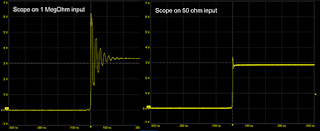
Fast buffered signal over a 1 megaohm input, and same signal over 50 ohm input
Figure 1. The same signal from a fast-buffer driver
measured with a 1-meter, 50 ohm cable with
1 megaohm input to the scope, and
same cable with 50 ohm input to the scope.
When every oscilloscope has both a 50 Ohm input and a 1 MOhm input, how do you choose which one to use? Here are my recommendations for when each input should be used. 

For additional information on this topic, check out my webinar on What Every Oscilloscope User Needs to Know About Transmission Lines.  

19 December 2018

Using 50-Ohm Coax From DUT to Oscilloscope

A coaxial cable presents high impedance at low frequencies but acts as a transmission line at higher frequencies
Figure 1: A coaxial cable presents high impedance at low
frequencies but acts as a transmission line at higher frequencies
In our recent exploration of 10x passive probes, we've determined that while these types of probes are great general-purpose tools, they're not necessarily going to do the job in specialized measurement circumstances. They're relatively low-bandwidth, low-SNR probes that impose some limitations and, in some scenarios, can deliver potentially misleading or erroneous measurement results if used without clear understanding of their capabilities.

01 November 2018

How Equalization Works in 10x Passive Probes

The adjustable equalization circuit on the oscilloscope end of the coaxial cable compensates for the 10x passive probe's inherent low-pass filter characteristics
Figure 1: The adjustable equalization circuit on the oscilloscope
end of the coaxial cable compensates for the 10x passive
probe's inherent low-pass filter characteristics
We've been discussing 10x passive probes and their inner workings; our last post covered all the ways in which a 10x passive probe is apt to be a liability. They'd be basically unusable for any measurements at all but for one attribute: their equalization circuit (Figure 1). Without it, the 10x passive probe makes a pretty good low-pass filter, but the equalization circuit counters that with a high-pass filter to balance things out.

01 March 2018

Transmission Lines (Part V): Reverse-Engineering the DUT
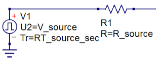
Every DUT can be thought of as a Thevenin voltage source with some internal resistance
Figure 1: Every DUT can be thought of as a Thevenin
voltage source with some internal resistance
There are always two primary elements of any test and/or measurement application: the oscilloscope and the device under test (DUT). Getting valid measurement results depends, first and foremost, on the oscilloscope's capabilities given the task at hand. It also depends on what we'll call "situational awareness," or the operator's understanding of the oscilloscope and of the characteristics of the DUT.

19 January 2018

Bandwidth vs. Current Load in Power-Rail Measurements

Connecting a 6" length of coaxial cable between a low-impedance DUT and a 1-MΩ produces ringing artifacts on your signal acquisition
Figure 1: Connecting a 6" length of coaxial cable between
a low-impedance power rail and a 1-MΩ input impedance
produces reflections and ringing artifacts
on your signal acquisition
Among the various challenges we've discussed in measuring noise on power rails are RF pickup and signal-to-noise ratio (SNR). Here's another: how do you achieve high bandwidth in your measurements while also minimizing current load on your DUT? Given that your DUT is a power rail, you really don't want to draw too much current from it. But these two measurement criteria are at loggerheads with each other. It's a quandary, and it has to do with the fundamental nature of signals on interconnects.

20 November 2013

Back to Basics: Probes (Part II)

In a previous post, we provided some basic information about oscilloscope probes, including a brief survey of the different types and what can happen when the probe is connected to a DUT. In this installment, let's continue along those lines and take a closer look at passive probes.

13 November 2013

Back to Basics: Probes (Part I)
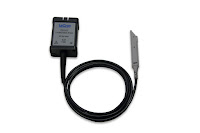
An example of an active oscilloscope probe
Figure 1: An example of an active
oscilloscope probe 
To speak of an oscilloscope probe is to open a fairly large can of worms. There are many kinds of probes on the market, with differing functions and characteristics (Figure 1). This is the first in a short series of posts on the basics on probes, what the various kinds are used for, and how they might be expected to affect measurements taken with them.