You need to test, we're here to help.

You need to test, we're here to help.
Showing posts with label transmission lines. Show all posts

31 January 2022

Transmission Lines for Oscilloscope Users, Part 2

Figure 1: A transmission line can be seen as a series of "buckets" of capacitance charged to a voltage by the signal as it "walks the line."
Figure 1: A transmission line can be seen as
a series of "buckets" of capacitance charged
to a voltage by the signal as it "walks the line."
In Part 1, we experimented with the signal rise time measurement and saw that it appeared to increase substantially as the length of the interconnecting cable was increased. To understand why, we revisited some basic principles of signal integrity:

1. All interconnects are transmission lines. 
2. Signals are dynamic, and once launched, cannot be prevented from propagating down the transmission line.

Be the Signal

To illustrate the dynamic nature of signals, imagine a very simple, 1 ns long, 50 Ω impedance transmission line. As a 1 V signal is launched into the transmission line and propagates, at each step along the way it asks "What's the impedance of the environment?" at its leading edge. That is the instantaneous impedance, notated as Z. Impedance is always defined as the ratio of a voltage to a current. We know the voltage of this signal (1 V), but how do we find the current at the edge? 
24 January 2022

Transmission Lines for Oscilloscope Users, Part 1

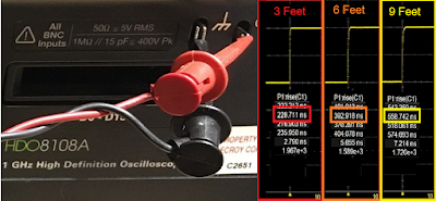
Figure 1: The rise time of the Cal signal seems to increase significantly by increasing the length of the interconnect cable. Is it true? Click image for details.
Figure 1: The rise time of the Cal signal seems to
increase significantly by increasing the length of the
interconnect cable. Is it true? Click image for details.
This post is the first of a series that will discuss what every oscilloscope user needs to know about transmission lines. It is going to introduce you to the absolutely most important signal integrity principles everybody needs to know when using an oscilloscope to measure signals with rise times shorter than 10 nanoseconds. After demonstrating some easily misinterpreted measurements, we’re going to look “under the hood” at what’s really happening to show you how it's all about the principles of transmission lines. Awhile back, Dr. Eric Bogatin offered a condensed version of What Every Oscilloscope User Needs to Know About Transmission Lines that summed up the key takeaways, but by revisiting “Transmission Lines 101” with us here, we’ll hopefully also show you a different way of thinking about your measurements.

15 June 2020

What Every Oscilloscope User Needs to Know About Transmission Lines

Eric Bogatin, Signal Integrity Evangelist, Teledyne LeCroy

Measured voltage at the oscilloscope from a fast edge, low impedance DUT, with the oscilloscope at 1 megaohms (left) and 50 ohms (right).
Figure 1. Measured voltage at the oscilloscope from a
fast edge, low impedance DUT, with the oscilloscope at
1 megaohms (left) and 50 ohms (right).
It is easy to take a measurement with an oscilloscope and see a voltage waveform on the screen. It is sometimes hard to take a measurement without artifacts and interpret all the details of the measurement. 

Whenever you measure a signal with a rise time shorter than about 20 ns, assuming a 1 m long coax cable, transmission line effects should pop to the top of your list of potential artifacts to consider and avoid. 

07 August 2018

About Ground Bounce and How to Measure It

Shown are five I/O drivers within a package driving signal lines on a PC board
Figure 1: Shown are five I/O drivers
within a package driving signal
lines on a PC board
Designing and/or troubleshooting a system with, say, an MCU driving signals across transmission lines, can be an interesting exercise in patience and diligent sleuthing. Perhaps you're seeing an inordinate amount of bit errors at the receive end of I/O lines but having some difficulty nailing down the source. In many cases, the problem is ground bounce, an issue that can be tough to diagnose and cure. Let's begin an examination of the ground-bounce phenomenon by explaining how it arises and then outlining an approach for finding it.

06 June 2018

A Look at Transmission-Line Losses

Using a 3D field solver to simulate a differential trace
Figure 1: Using a 3D
field solver to simulate
a differential trace
In surveying the subject of debugging high-speed serial data links, we've noted that there's no one cause for signal-integrity issues between transmitter and receiver, and there's certainly no one solution. But let's begin with the low-hanging fruit: electrical losses in the transmission line. We've previously done a series of posts on transmission lines (beginning here), but it's worth it to have a quick refresher.