We've routinely posted on how you can characterize your total measurement system to gain important "situational awareness" when using an oscilloscope to make sensitive measurements. The knowledge gained from these tests helps you properly interpret your measurement results so that you can deduce what is actually going on with your circuit, versus what is an artifact of the measurement system. Listed here are nine important things you should know before making sensitive measurements with your oscilloscope, with links to blog posts that instruct you how to test them.
You need to test, we're here to help.
05 April 2021
How to Test the CMRR of Differential Probes
 |
| Figure 1: CMRR plots for two attenuation settings of an HVD3106A differential probe. |
Although CMRR as a function of frequency is a principal specification for differential probes, manufacturer's CMRR plots are the result of testing with a narrowband source under strictly controlled laboratory conditions. In real-world applications of probes to broadband sources, you can expect a different result. This quick test will inform you how different.
22 February 2021
Don't Attach Multiple Probes to the Same Place at the Same Time!
 |
| Figure 1. Response of two different probes to an upper-side gate drive measurement. |
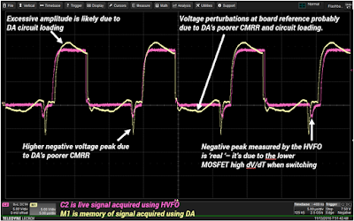
You are probably aware that all measuring instruments, including oscilloscopes, are subject to conditions of observability. As we discussed in a recent post on The Impact of the Interconnect, the very act of connecting the oscilloscope to the circuit with a particular probe affects the measurement in a particular way. Probes affect the circuit by applying additional resistance and capacitance loads in parallel with the circuit at the test point. Moreover, the probes themselves limit the fidelity of the measurement due to limits of bandwidth, slew rate and common mode response. So, it is always a good idea when making a measurement to compare how different probes/interconnects will affect the measurement…but don’t try to do it all at once.
09 June 2015
Testing Techniques For Switch-Mode Power Supplies
 |
| Figure 1: A simplified schematic of a switch-mode power supply circuit |
12 December 2013
Back to Basics: Probes (Part IV)
 |
| Figure 1: An example of differential probes measuring from test point to test point. |
23 July 2013
Back to Basics: Differential Probing
 |
| Figure 1: Emitter voltage measurement in simplified schematic view |