You need to test, we're here to help.

You need to test, we're here to help.
Showing posts with label solder-in probe tips. Show all posts

17 January 2022

9 Quick Fixes to Improve DDR Probing

Figure 1: Reversed Handsfree mounts and chip clips help relieve strain on fragile solders.
Figure 1: Reversed Handsfree mounts and chip
clips help relieve strain on fragile solders.
Probing at DRAM pins as required by JEDEC can be challenging. Here are nine, simple ways to improve your DDR probing.

1. Use positioning tools to relieve strain on probe tips

The Handsfree probe holder included as an accessory with several Teledyne LeCroy probes, such as the WaveLink and DH Series probes, was originally designed to put weight on the probe tip to ensure a good contact. However, many DDR probing applications utilize solder-in (SI) tips, where the greater concern is to relieve strain on the tip so as to not disrupt the solder. It turns out that if you use the Handsfree in a “reverse mounted” orientation (Figure 1), it puts the amplifier in a perfect position to help relieve strain on probe tips.

19 May 2017

Testing the DDR Memory Interface's Physical Layer (Part IV)

Probes are a key element of the total signal acquisition system
Figure 1: Probes are a key element of the total signal
acquisition system
In this multipart survey of testing the DDR interface's physical layer, we've looked at the basics of the interface itself, a high-level overview of the testing, how to access DDR signals, and read/write burst separation. In this installment, we'll cover preparation for the actual testing.

01 October 2014

DDR Memory Testing Part II: Using Interposers

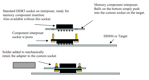
The anatomy of a chip interposer
Figure 1: The anatomy of a chip interposer
If you're a PCB layout designer, you've probably heard one or more test engineers complain: "Why can't you lay out the board so that it can be tested?" All too often, components that need to be accessible to oscilloscope probes are physically inaccessible, whether it's because of close proximity of adjacent components or ball grid array (BGA) mounting of the DUT. It's nearly always a necessary evil, though, because of PCB cost and/or mechanical constraints.