You need to test, we're here to help.

You need to test, we're here to help.
Showing posts with label jitter. Show all posts

10 October 2022

Oscilloscope Testing of 10Base-T1S Automotive Ethernet Signal Integrity

Eye diagram generated from decoded 10Base-T1S signal
Figure 1. The 10Base-T1S TDME option features
easy eye diagram creation for signal integrity analysis.
Click on any image to enlarge it.
In addition to special serial data bus measurements of 10Base-T1S signals, the 10Base-T1S Trigger, Decode, Measure/Graph & Eye Diagram (TDME) option automates the generation and display of eye diagrams on Teledyne LeCroy oscilloscopes. Eye diagrams are an important element of serial data analysis, used to understand the signal integrity of the communications network. 

The eye diagram is a general-purpose tool for analyzing serial digital communications signals. It shows the effects of additive vertical noise, horizontal jitter, duty cycle distortion, inter-symbol interference, and crosstalk on a serial data stream. 

The eye diagram is formed by overlaying repetitive occurrences of slightly more than a single clock period (UI) of a serial data signal on a persistence display which shows the accumulated history of multiple acquisitions, as shown in Figure 1.

Due to the use of Differential Manchester encoding (DME), the 10Base-T1S eye is formed with twice the signal clock rate. The signal shown has a symbol rate of 12.5 Mbps and the eye is clocked at 25 Mbps. 

12 July 2021

MAUI Studio Pro: Generating Waveforms

Figure 1: MAUI Studio Pro lets you generate multiple waveform types from equation.
Figure 1: MAUI Studio Pro lets you generate
multiple waveform types from equation.
MAUI® Studio includes a simple waveform generator that enables you to create any of six standard waveforms or a DC current simply by enter a few waveform properties, such as frequency and amplitude. The waveforms are continuously generated and act like a live, repetitive waveform acquisition for simulation exercises. 

MAUI Studio Pro adds to that a true, arbitrary function generator. Numerous different waveform types can be generated from equation, and custom jitter/noise characteristics can be added to any generated waveform. 

19 September 2017

Automotive Ethernet Compliance: Tests in Detail (Part II)

Figure 1: Testing transmitter timing master jitter entails creating a track of TIE measurements
Figure 1: Testing transmitter timing master jitter
entails creating a track of TIE measurements
We've begun our deep dive into the subject of Automotive Ethernet compliance testing. In our last post, we covered the first two of seven tests: maximum transmitter output droop and transmitter clock frequency. Let's now look at transmitter timing jitter in master and slave modes.

12 August 2015

Test Challenges for PAM4 Signals

The major test challenges posed by PAM4 signals
PAM4 encoding offers the advantage of doubling the bit rate in a serial data channel, doing so by increasing the number of voltage levels from two to four. It's a fairly complex modulation scheme, so it should be no surprise that it presents some test and measurement challenges.

19 May 2015

The History of Jitter (Part IV)

An example of a time-interval error track
Figure 1: An example of a time-interval error track
In the previous installment in this series on the history of jitter, we'd reached the cusp of the new millennium. The in-vogue methodology for jitter analysis of the day was using edge crossing-point data in the form of a histogram and fitting Gaussian functions to the tails of the plot. But tail fitting, as we well know, isn't for the faint of heart. How would test methodologies move forward to surmount that hurdle?

02 April 2015

The History of Jitter (Part III)

Latching a signal at the outermost of the blue hash marks results in a BER of 10-3, while latching it at the innermost hash marks yields a BER of 10-12
Figure 1: Latching a signal at the outermost of the blue
hash marks results in a BER of 10-3, while latching it
at the innermost hash marks yields a BER of 10-12
If you've been keeping track of our history of jitter, we left off in Part II in the late 1990s, by which time bit-error rates (BER) had become a predominant statistic for quantifying jitter. That was subsequently refined into thinking in terms of BER as a function of jitter.

12 March 2015

The History of Jitter (Part II)

An example of using histograms to plot the statistical distribution of edge arrival times
Figure 1: An example of using histograms to plot
the statistical distribution of edge arrival times
Resuming our review of the history of jitter and the evolving response to it, we'd arrived at the late 1990s, when more sophisticated analysis methods were necessary to get a good handle on jitter. In particular, statistical analysis came onto the scene. Statistics are a great tool for analyzing phenomena such as jitter that change more as you look at them harder.

05 March 2015

The History of Jitter

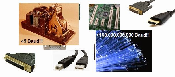
The story of jitter spans 45-baud telegraph machines to 160-Gbaud optical fiber
Figure 1: The story of jitter spans 45-baud telegraph
machines to 160-Gbaud optical fiber
Jitter is a signal-integrity gremlin that's been with us for a long time. In fact, it's been with us since before anyone really needed to care about it. But as time has worn on, our perception of jitter has certainly changed, and with it our approaches to diagnosing it, measuring it, and ultimately dispatching it. Here, we'll begin a traversal of the "jitter story," surveying where we've been, where we are, and where we may be going in our dealings with the phenomenon.

26 January 2015

Plan For Successful USB Compliance Testing (Part II)

A representative transmitter compliance test setup
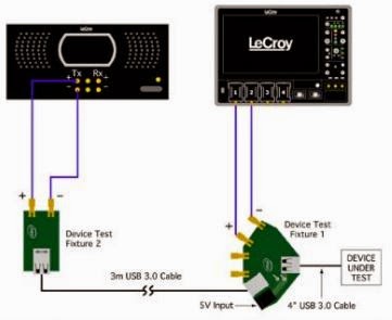
Figure 1: A representative transmitter
compliance test setup
In the first post in this series, we looked at some of the basics of USB 3.0 and 3.1 compliance test and covered the USB-IF's role in overseeing the protocol. Now, let's look into some aspects of physical-layer test.

05 March 2014

Measuring Time-Interval Error in Serial Data Waveforms

Measured times of arrival
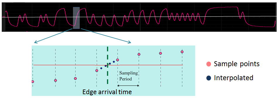
Figure 1: The first step in quantifying jitter is to
determine measured times of arrival for bit transitions
A recent post covered some of the reasons why one might want to measure jitter. In design and debug of serial-data channels, jitter is among the most prevalent causes of unacceptable bit-error rates (BERs). In that earlier post, we looked at the physical phenomenon of jitter and why it wreaks the havoc that it does. In the present installment, we will look in broad terms at how jitter is measured and quantified.

05 February 2014

Why Should You Measure Jitter?

Typical channel with jitter sources
Figure 1: Designing a serial-data channel with first-pass
success means analysis and mitigation of jitter sources
As mentioned in an earlier post on some basics of jitter, the bane of serial-link design is a signal that doesn't arrive at its destination when it should, whether early or late. The goal of serial-link design and implementation is to transmit data with as few bit errors as possible. Thus, analyzing jitter is a key element of achieving first-pass design success.

22 January 2014

The Components of Total Jitter

Figure 1: An overview of the jitter hierarchy, or "jitter tree," showing the various elements that make up total jitter
Figure 1: An overview of the jitter hierarchy,
or "jitter tree," showing the various elements
that make up total jitter
In an earlier post, we began looking at the topic of jitter, a topic of keen interest to anyone working with high-speed serial communications or the components of such a system, including transmitters, receivers, and data channels. To gain an understanding of jitter, an important first step is getting to know a little about the various categories that comprise total jitter.

23 December 2013

Back to Basics: Jitter

Jitter defined
Figure 1: Jitter is short-term variation
of a signal with respect to its
ideal position in time
Anyone working in applications that involve digital data, clocks, and serial data in general will eventually bump up against issues concerning jitter. Jitter is a subject of keen interest to every strata of the electronics industry. Chip makers, board integrators, system integrators, you name it: Everybody wants, and needs, to come to terms with jitter. It impacts reliability, manufacturability, and cost at all levels. And, of course, it's of keen interest to purveyors of test instruments, including us here at Teledyne LeCroy. In this first post of a projected series on jitter, we'll look at some of the tools built into modern digital oscilloscopes for jitter measurement and analysis.