 |
| Figure 1: Maximum transmitter output droop should not exceed the specified maximum of 45% |
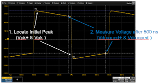
The first test is for maximum transmitter output droop and is performed using test mode #1. The test measures both positive and negative transmitter output droop and compares it to the test limit of 45%. If you pay regular attention to the BroadR-Reach specification, you'll note that the test limit for this parameter has varied over the years. It began at 45%, then was reduced to 26.9%, and then reset at 45%.
 |
| Figure 2: Locating the initial positive and negative transmit peaks and measuring Vdrooped 500 ns later |
Once you have values for Vpk+ and Vpk-, calculate droop as = 100 x (Vdrooped/Vpk), and compare the result to the test limit of 45%.
In the second test, which is for transmitter clock frequency, we will verify that the frequency of the transmitted clock meets the specification. This test uses test mode #2, which comprises a sine wave transmitted from the device in master transmission mode. The test limit for symbol transmission rate is 66.66 Mbaud ±100 ppm.
Fortunately, the transmitter clock frequency test is a simple matter. If your oscilloscope is so equipped, simply turn on measurement of the frequency (or bit rate) parameter. If, for instance, you're measuring a nominal 33.3-MHz clock, you would create a pass/fail condition with an absolute delta (being a plus/minus range that accommodates the 100-ppm window). Note that 33 MHz is half the baud rate, because it takes two symbols to create one cycle.
In our next installment, we'll turn to the transmitter timing jitter (master and slave, respectively).
3 comments:
I recently came across your blog and have been reading along. I thought I would leave my first comment. I don’t know what to say except that I have enjoyed reading. Nice blog, I will keep visiting this blog very often. revs
Thanks for this article.
Also, please let us know under what conditions, droop > 45%. what are the debug points to check why such an issue could have happened?
gowrishankargupta, apologies for the great delay in replying.
The Test Mode 1 pattern leaves the transmitter as a square wave. The Transmitter Output Droop test is performed at the connector to verify that the signal arrives with not more than a 45% drop in amplitude (droop).
Between these two points, the signal goes through a Low-pass Filter (LPF) and Common Mode Choke (CMC). This filtering is often designed to alleviate EMI/EMC issues on the signal path.
The droop test is performed to ensure that there is not excessive filtering happening between the transmitter output and the MDI output (connector). If the droop is > 45%, the LPF and/or the CMC are excessively impacting the signal and need adjustment so that the effect is not as extreme.
Post a Comment