 |
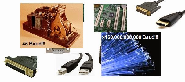
| Figure 1: The story of jitter spans 45-baud telegraph machines to 160-Gbaud optical fiber |
There's no simple, straight path through the history of jitter. Rather, it's a story of numerous instruments, inventors, and twists and turns. We know, however, that it is borne of the ascent of serial data rates from a 45-baud telegraph receiver to the venerable 9-pin serial port to optical fiber carrying signals out to 160 Gbaud and up (Figure 1). Along the way, we've seen real-time oscilloscopes, sampling oscilloscopes, time-interval analyzers, phase-noise analyzers, and bit-error-rate (BER) testers thrown at the problem in our efforts to understand and tame it.
 |
| Figure 2: Jitter happens when data edges and their associated clock signals aren't marching in step |
In the early days of digital logic—the 1960s—the issue surrounding timing measurements and proper latching concerned setup and hold times. Investigation of setup and hold performance was relatively straightforward, even with the analog oscilloscopes of the day. One would trigger on the clock and measure the time from one edge to the next using cursors. In other words, you'd try to duplicate the timing diagrams on the datasheet to see if you fell within the requisite timing margins.
 |
| Figure 3: Remember the carefree 70s and 80s, when no one really cared very much about jitter? |
But by the late 1990s, the scenario was very different with respect to jitter. The transition from parallel to serial data buses was well underway. Data rates had climbed into the gigabits/s range while rise times had dropped into the hundreds of picoseconds. As a result, a little fuzziness on a rising or falling edge had become much more significant with respect to the entire unit interval.
Thus, in the late 1990s, the question had become, "How do I characterize setup and hold times with any real level of certainty?" Which is to say, how much jitter is there? Ah, NOW it matters! One simplistic method that gained prevalence was to measure the peak-to-peak jitter on eight clock edges. Obviously, this is not a particularly accurate method, as there will be a good amount of variation on any eight given edges of a clock output. One thing had become clear: Jitter affects setup and hold margins. The longer we measure for, the shorter setup and hold times become, and the tighter the margins become.
Around this time, some advances in measurement technology arrived that allowed edge times to be analyzed with a bit more detail. Stay tuned for subsequent posts that continue the story of jitter.
No comments:
Post a Comment