You need to test, we're here to help.

You need to test, we're here to help.
Showing posts with label physical layer test. Show all posts

27 June 2022

Get Ready for PCIe 6.0 Base Tx Testing--Compliance, Jitter and Eye Diagrams

Figure 1. The four levels and three eyes of the PCIe 6.0 PAM4 signal. Click on any image to enlarge.
Figure 1. The four levels and three eyes of the
PCIe 6.0 PAM4 signal.
Click on any image to enlarge.
The PCI Express® 6.0 Base specification was officially released in January 2022 at version 1.0, meaning it is considered final. The CEM and PHY test specifications are currently at version 0.3, and 0.5 versions of both will probably be released sometime in the third or fourth quarter of 2022. As both the CEM and PHY test specifications are still at an early stage, it's hard to predict exactly when the PCIe® 6.0 compliance test program will start, but it's safe to say it is at least a few years out. However, PCIe 6.0 Base testing is upon us, especially those of us working on chip design.

So, what can implementers expect as they retool for PCIe 6.0 Base Tx and Base Rx physical layer testing?

15 March 2021

The Important Difference Between ProtoSync™ and CrossSync™ PHY

Figure 1: CrossSync PHY captures everything from physical through protocol layers at once.
Figure 1: CrossSync PHY captures everything from
physical through protocol layers at once.
With the recent release of our new CrossSync™ PHY for PCI Express® product, some of you may be wondering how it’s any different than ProtoSync™ for PCIe®, which has been around for quite a few years.

ProtoSync is an option for Teledyne LeCroy oscilloscopes with bandwidths that support high-speed serial data analysis. We’ve released ProtoSync options for PCIe, USB, SAS/SATA and Fibre Channel. ProtoSync links the same Protocol Analysis Suite software that is used with our protocol analyzers to the oscilloscope application, so that you can see physical layer decodings in the familiar PETracer and BITracer views right next to the decoded analog waveform. 

CrossSync PHY differs from ProtoSync in the three, significant ways:

17 January 2018

A Tour of a PCIe 3.0 Test Setup

Test-equipment requirements for PCIe 3.0
Figure 1: Test-equipment requirements for PCIe 3.0
Having examined the complex machinations of PCIe 3.0 dynamic link equalization in earlier posts (see the links below), now we will look at a typical test setup for design and debug and/or compliance testing. Then we will move on to some test examples showing some common problems that one might encounter.

30 August 2017

Automotive Ethernet Compliance: The Five Test Modes

Automotive Ethernet electrical compliance test is defined at the connector of the transmitter
Figure 1:Automotive Ethernet electrical compliance test
is defined at the connector of the transmitter
Following up on our introduction to Automotive Ethernet compliance testing, let's move on to an overview of the five test modes that comprise the compliance test suite for the 100Base-T1 protocol. The test modes allow for a common pattern to test stressful conditions across all devices. Testing in this fashion offers the best possible odds for achieving true interoperability.

24 April 2017

Testing the DDR Memory Interface's Physical Layer (Part III)

For analysis purposes. it's critical to separate read and write bursts of interest
Figure 1: For analysis purposes. it's critical to separate
read and write bursts of interest
Last time around, we began examining some of the challenges that come with testing the DDR interface's physical layer. In that post, we concentrated on getting to the devices' physical connections by various means including interposers, backside vias, and DIMM series resistors. Now, presuming we've managed to gain access to the DDR's ball-grid array, the next hurdle is separation of read and write bursts.

05 April 2017

Testing the DDR Memory Interface's Physical Layer (Part I)

Clock, strobe, and data are three critical signals in DDR test
Figure 1: Clock, strobe, and data are
three critical signals in DDR test
In an earlier post, we took a brief tour through what constitutes a DDR memory interface: clock, command, address, and strobe+data lines linking a memory controller and an array of DRAM memory ICs. Next, we'll examine what DDR interface testing is all about, concentrating primarily on the physical layer.

26 January 2015

Plan For Successful USB Compliance Testing (Part II)

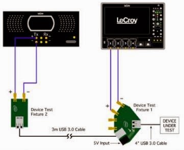
A representative transmitter compliance test setup
Figure 1: A representative transmitter
compliance test setup
In the first post in this series, we looked at some of the basics of USB 3.0 and 3.1 compliance test and covered the USB-IF's role in overseeing the protocol. Now, let's look into some aspects of physical-layer test.

16 January 2015

Plan For Successful USB Compliance Testing (Part I)

The coveted USB 3.1 logo
Figure 1: The coveted SuperSpeed USB logo
Certifying a device's implementation of a serial protocol standard is a fairly complex process involving a number of levels: electrical test, interoperability, backward compatibility, link layer, and so on. Generally, some organization oversees a given protocol, managing the revision process for the protocol itself as well as the testing process that a product must undergo. Passing the relevant compliance test suite and having a valid Trademark License Agreement on file bestows the prized right to display the protocol's logo on the product's box (Figure 1). That logo's presence tells the product's users that their device's serial interface operates within parameters set by the overseeing organization.