You need to test, we're here to help.

You need to test, we're here to help.
Showing posts with label bit error rate. Show all posts

16 January 2018

An Under-The-Hood View of PCIe 3.0 Link Training (Part II)

A diagrammatic view of the PCIe 3.0 dynamic link training process
Figure 1: A diagrammatic view of the
PCIe 3.0 dynamic link training process
Our last post in this series began examining the recovery.equalization process of PCIe 3.0 dynamic link training, beginning with Phases 0 and 1 of the process (Figure 1). Next, we will move on to take a closer look at Phases 2 and 3, where we'll see what can happen with devices in which the algorithms are not up to par. Namely, issues such as packet errors, dropped packets, and link retraining at lower data rates than 8 Gb/s.

01 March 2016

What Is An Optical Modulation Analyzer?

A representative block diagram of a coherent transmitter and receiver
Figure 1: A representative block diagram of a coherent
transmitter and receiver
In an earlier post, we looked at some of the fundamentals of coherent signals: what comprises a coherent signal, how and why they're used, and a bit about how they're represented visually on an oscilloscope. The advent of coherent signals has brought about the rise of a new class of test instrumentation, known as an optical modulation analyzer (OMA). In this post, we'll examine what an OMA is and what it brings to the party above and beyond a stand-alone oscilloscope.

02 April 2015

The History of Jitter (Part III)

Latching a signal at the outermost of the blue hash marks results in a BER of 10-3, while latching it at the innermost hash marks yields a BER of 10-12
Figure 1: Latching a signal at the outermost of the blue
hash marks results in a BER of 10-3, while latching it
at the innermost hash marks yields a BER of 10-12
If you've been keeping track of our history of jitter, we left off in Part II in the late 1990s, by which time bit-error rates (BER) had become a predominant statistic for quantifying jitter. That was subsequently refined into thinking in terms of BER as a function of jitter.

12 March 2015

The History of Jitter (Part II)

An example of using histograms to plot the statistical distribution of edge arrival times
Figure 1: An example of using histograms to plot
the statistical distribution of edge arrival times
Resuming our review of the history of jitter and the evolving response to it, we'd arrived at the late 1990s, when more sophisticated analysis methods were necessary to get a good handle on jitter. In particular, statistical analysis came onto the scene. Statistics are a great tool for analyzing phenomena such as jitter that change more as you look at them harder.

05 March 2015

The History of Jitter

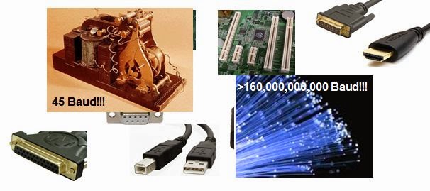
The story of jitter spans 45-baud telegraph machines to 160-Gbaud optical fiber
Figure 1: The story of jitter spans 45-baud telegraph
machines to 160-Gbaud optical fiber
Jitter is a signal-integrity gremlin that's been with us for a long time. In fact, it's been with us since before anyone really needed to care about it. But as time has worn on, our perception of jitter has certainly changed, and with it our approaches to diagnosing it, measuring it, and ultimately dispatching it. Here, we'll begin a traversal of the "jitter story," surveying where we've been, where we are, and where we may be going in our dealings with the phenomenon.

26 January 2015

Plan For Successful USB Compliance Testing (Part II)
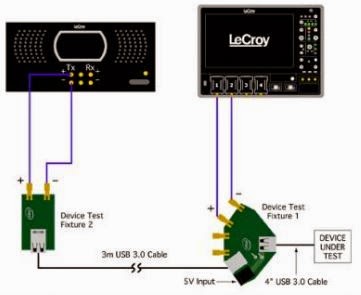
A representative transmitter compliance test setup
Figure 1: A representative transmitter
compliance test setup
In the first post in this series, we looked at some of the basics of USB 3.0 and 3.1 compliance test and covered the USB-IF's role in overseeing the protocol. Now, let's look into some aspects of physical-layer test.

14 November 2014

An Under-the-Hood View of PCIe 3.0 Link Training (Part I)

An overview of the elements of PCIe 3.0 dynamic link equalization
Figure 1: An overview of the elements of PCIe 3.0
dynamic link equalization
Now that we've looked at the basics of PCIe 3.0 dynamic link equalization and at some of the particulars of de-emphasis and preshoot, it's time to dive a little deeper into what actually happens in the link training process. It all happens in the blink of an eye but there's enough going on to warrant some dissection.

05 February 2014

Why Should You Measure Jitter?

Typical channel with jitter sources
Figure 1: Designing a serial-data channel with first-pass
success means analysis and mitigation of jitter sources
As mentioned in an earlier post on some basics of jitter, the bane of serial-link design is a signal that doesn't arrive at its destination when it should, whether early or late. The goal of serial-link design and implementation is to transmit data with as few bit errors as possible. Thus, analyzing jitter is a key element of achieving first-pass design success.