You need to test, we're here to help.

You need to test, we're here to help.
Showing posts with label power-rail measurement. Show all posts

20 September 2021

Testing Power Rail Sequences in Complex Embedded Systems

Figure 1. Four power rail signals on a single grid, with cursors measuring the time delay between the first pair in the sequence.
Figure 1. Four power rail signals on a single grid, with cursors
measuring the time delay between the first pair in the sequence.
Embedded computing systems generally require multiple supply voltages to deliver power to the microprocessor, memory and other on-board devices. There is usually a 12- or 15-volt DC primary supply, and numerous buck or boost converters working off the primary to help provide various voltages throughout the embedded system. Most microcontrollers have a prescribed order in which the voltages must be applied to prevent problems like lockups, so an area of concern when designing deeply embedded systems is the proper sequencing of power rails as they power up or down. Power management IC’s (PMIC) or power sequencers perform many of the sequencing tasks, but during validation and when troubleshooting, the order and timing of the power sequence should be verified.

09 November 2020

Fundamentals of Power Integrity: Mutual Aggressors and Rail Transient Response Measurement

Fig 1. Rail droop in response to a load step is a typical case of mutual aggressors in a PDN.
Fig 1. Rail droop in response to a load step is
a typical case of mutual aggressors in a PDN.
A third type of noise found in PDNs is what we call mutual aggressors, which is crosstalk coupling from one component of the PDN onto another.

An obvious example is a load step in the PDA, where something in the system being turned on pulls current from the VRM that supplies a rail. In Figure 1, you can see how the output voltage of the VRM supplying a 1 V rail droops in response to a load step before it recovers. This is still noise: it is a signal variation that we're not expecting and don't want.

We want to be able to characterize that noise, because too much droop could affect the operation of other components that are already consuming power from that device.

In order to do so, we’re going to measure the rail transient response to the load application. We need only look at two signals: the voltage and the current on the rail of interest. Figure 1 shows the voltage on C5 (the green trace) and the current on C8 (the orange trace).

31 August 2020

Fundamentals of Power Integrity: Characterizing PDN Noise

Figure 1. Noise tolerances for embedded system components are becoming ever tighter.
Figure 1. Noise tolerances for embedded system
components are becoming ever tighter.
Power integrity concerns maintaining the quality of power from generation to consumption in an embedded system. “Good” power integrity could be defined as having noise levels that are within tolerance. This short series will focus on characterizing noise on your power delivery network (PDN), with the goal of knowing where you must adjust your design to meet those tolerances.

Why do we care about voltage rail noise? As electronic designs strive for ever lower power consumption, power rails already carry very low voltages, often 1 V or less. Components like RF receivers, ADCs and DACs can be affected by noise of less than 1% of the rail value (Figure 1). This means noise tolerances can be as tight as single-digit millivolts, which is why power integrity takes up considerable validation time in labs.

19 January 2018

Bandwidth vs. Current Load in Power-Rail Measurements
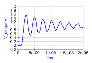
Connecting a 6" length of coaxial cable between a low-impedance DUT and a 1-MΩ produces ringing artifacts on your signal acquisition
Figure 1: Connecting a 6" length of coaxial cable between
a low-impedance power rail and a 1-MΩ input impedance
produces reflections and ringing artifacts
on your signal acquisition
Among the various challenges we've discussed in measuring noise on power rails are RF pickup and signal-to-noise ratio (SNR). Here's another: how do you achieve high bandwidth in your measurements while also minimizing current load on your DUT? Given that your DUT is a power rail, you really don't want to draw too much current from it. But these two measurement criteria are at loggerheads with each other. It's a quandary, and it has to do with the fundamental nature of signals on interconnects.

18 January 2018

Understand RF Pickup When Measuring Power Rails

Teledyne LeCroy's  HDO8108A sports a very low  noise floor of about 145 μV
Figure 1: Teledyne LeCroy's
HDO8108A sports a very low
noise floor of about 145 μV 
Measuring the noise on a power rail seems to be a straightforward task. However, there are some basic pitfalls that can cause incorrect, or even downright strange, results. Let's look at one of these challenges: RF pickup. We'll demonstrate the effect of RF pickup on a power-rail measurement, and then we'll show you an effective means of mitigating that effect.