
We've routinely posted on how you can characterize your total measurement system to gain important "situational awareness" when using an oscilloscope to make sensitive measurements. The knowledge gained from these tests helps you properly interpret your measurement results so that you can deduce what is actually going on with your circuit, versus what is an artifact of the measurement system. Listed here are nine important things you should know before making sensitive measurements with your oscilloscope, with links to blog posts that instruct you how to test them.
21 February 2022
14 February 2022
Transmission Lines for Oscilloscope Users, Part 4
 |
| Figure 1: Characteristic waveform when the source impedance is lower than the cable impedance. |
For this example, the source voltage is a 3.3 V square wave and the source impedance is 9 Ω. As before, our transmission line is a 50 Ω coaxial cable connecting the source to the oscilloscope. If the oscilloscope input termination is set to 1 MΩ, we see the interesting waveform shown in Figure 1.

07 February 2022
Transmission Lines for Oscilloscope Users, Part 3
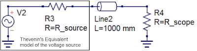 |
| Figure 1: The Thevenin equivalent circuit model can be used to characterize a voltage source with respect to the interconnect cable and oscilloscope input termination. |
Two terms needed for us to characterize the source are the Thevenin source voltage and the Thevenin source resistance. Once we know these, we have all the pieces we need to fully understand what is happening with our measurements. This is true whether the signal source is a Cal terminal or a device-under-test.
31 January 2022
Transmission Lines for Oscilloscope Users, Part 2
 |
| Figure 1: A transmission line can be seen as a series of "buckets" of capacitance charged to a voltage by the signal as it "walks the line." |
2. Signals are dynamic, and once launched, cannot be prevented from propagating down the transmission line.
Be the Signal
To illustrate the dynamic nature of signals, imagine a very simple, 1 ns long, 50 Ω impedance transmission line. As a 1 V signal is launched into the transmission line and propagates, at each step along the way it asks "What's the impedance of the environment?" at its leading edge. That is the instantaneous impedance, notated as Z. Impedance is always defined as the ratio of a voltage to a current. We know the voltage of this signal (1 V), but how do we find the current at the edge?
24 January 2022
Transmission Lines for Oscilloscope Users, Part 1
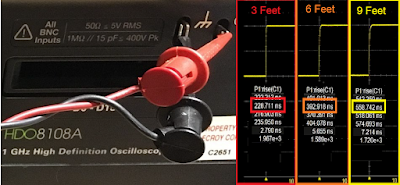 |
| Figure 1: The rise time of the Cal signal seems to increase significantly by increasing the length of the interconnect cable. Is it true? Click image for details. |
17 January 2022
9 Quick Fixes to Improve DDR Probing
 |
| Figure 1: Reversed Handsfree mounts and chip clips help relieve strain on fragile solders. |
1. Use positioning tools to relieve strain on probe tips
The Handsfree probe holder included as an accessory with several Teledyne LeCroy probes, such as the WaveLink and DH Series probes, was originally designed to put weight on the probe tip to ensure a good contact. However, many DDR probing applications utilize solder-in (SI) tips, where the greater concern is to relieve strain on the tip so as to not disrupt the solder. It turns out that if you use the Handsfree in a “reverse mounted” orientation (Figure 1), it puts the amplifier in a perfect position to help relieve strain on probe tips.
10 January 2022
Oscilloscope Basics: Stabilizing Waveform Display, Pt. 2
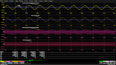 |
| Figure 1: A 50 kHz low-pass filter eliminates a 93 kHz interfering signal from a 10 kHz signal (top two grids) and a 50 kHz high-pass filter cleans up a 93 kHz signal with an additive 10 kHz interfering signal (bottom two grids). Click image to expand. |
Coupling
In the Setup section of the Trigger dialog, Trigger input sources can be conditioned using AC or DC coupling, high-pass filters (LFREJ for low-frequency reject) and low-pass filters (HFREJ for high-frequency reject). The frequency selective coupling paths are used to attenuate extraneous signals. The low-frequency reject inserts a 50 kHz high-pass filter in the trigger signal path, which is useful for eliminating low-frequency interference such as 60 Hz power mains signals. This low-frequency noise can cause erroneous triggers, resulting in an unstable display. The high-frequency reject inserts a 50 kHz low-pass filter. This coupling mode finds use in applications such as troubleshooting switch-mode power supplies, where it suppresses signals at the power supply switching frequency. Like any extraneous signal, high frequency pickup can leak into the input signal and cause trigger instability. Figure 1 provides examples of how the HFREJ and LFREJ coupling filters eliminate interfering signals from the trigger source.
Subscribe to:
Posts (Atom)