You need to test, we're here to help.

You need to test, we're here to help.
Showing posts with label oscilloscope triggering. Show all posts

16 May 2022

Oscilloscope Basics: External, Line and Fast Edge "Triggers"

An oscilloscope trigger synchronizes the oscilloscope timebase to the input signal so that the displayed trace is stable. In digital storage oscilloscopes, while the digitizer runs continuously converting analog voltage/current inputs to digital values, it is the trigger event that defines the “acquisition window,” marking the point where data is stored to acquisition memory, locking the signal data for display, measurement and further processing. 

Figure 1: The trigger setup showing the possible choices for the trigger source.

Triggers are set to fire based on the state of a trigger source waveform. What are commonly known as External, Line and Fast Edge "triggers" are not really different trigger types, per se, but alternative trigger sources.  Figure 1 shows the typical setup options for an Edge trigger, the most commonly used trigger type.  With Edge triggering, the oscilloscope is triggered when the source waveform crosses a user-defined threshold level and slope.  Usually, the source will be analog input channel C1-Cn. However, three other sources can be used to initiate an Edge trigger: an Ext(ernal) input, the Line (mains) power and, on some oscilloscopes, the built-in Fast Edge signal. 

10 January 2022

Oscilloscope Basics: Stabilizing Waveform Display, Pt. 2

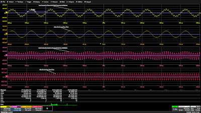
Figure 1: A 50 kHz low-pass filter eliminates a 93 kHz interfering signal from a 10 kHz signal (top two grids) and a 50 kHz high-pass filter cleans up a 93 kHz signal with an additive 10 kHz interfering signal (bottom two grids). Click image to expand.
Figure 1: A 50 kHz low-pass filter eliminates a
93 kHz interfering signal from a 10 kHz signal (top two grids)
and a 50 kHz high-pass filter cleans up a 93 kHz signal
with an additive 10 kHz interfering signal (bottom two grids).
Click image to expand.
In Pt. 1, we discussed the fundamental cause of unstable waveform displays. In this post, we’ll discuss how to use signal conditioners and conditional triggering to help the oscilloscope ignore extraneous samples when determining where the acquisition trigger event actually occurs.

Coupling 

In the Setup section of the Trigger dialog, Trigger input sources can be conditioned using AC or DC coupling, high-pass filters (LFREJ for low-frequency reject) and low-pass filters (HFREJ for high-frequency reject). The frequency selective coupling paths are used to attenuate extraneous signals. The low-frequency reject inserts a 50 kHz high-pass filter in the trigger signal path, which is useful for eliminating low-frequency interference such as 60 Hz power mains signals. This low-frequency noise can cause erroneous triggers, resulting in an unstable display. The high-frequency reject inserts a 50 kHz low-pass filter. This coupling mode finds use in applications such as troubleshooting switch-mode power supplies, where it suppresses signals at the power supply switching frequency. Like any extraneous signal, high frequency pickup can leak into the input signal and cause trigger instability. Figure 1 provides examples of how the HFREJ and LFREJ coupling filters eliminate interfering signals from the trigger source.

04 January 2022

Oscilloscope Basics: Stabilizing Waveform Display, Pt. 1

Figure 1: A free running oscilloscope starts each acquisition at a different point on the waveform, resulting in an unstable display.  A triggered oscilloscope starts each acquisition at the same point on the waveform, resulting in a stable display.
Figure 1: A free running oscilloscope starts each
acquisition at a different point on the waveform,
resulting in an unstable display.  A triggered oscilloscope
starts each acquisition at the same point on the
waveform, resulting in a stable display. 
An unsynchronized, unstable oscilloscope display is useless for making measurements, but proper triggering can synchronize the oscilloscope sample clock to specific waveform events so that the acquired waveforms appear stable on the display.  Let’s look at why signals can appear unstable and what to do about it.  

Oscilloscopes are sampling devices; they sample the incoming signal at a uniform rate.  The timing of a signal applied to the input of an oscilloscope is most probably asynchronous with the oscilloscope’s sampling clock.  If the oscilloscope timebase is allowed to run free—that is, not synchronized to the timing of the input signal—then each oscilloscope acquisition potentially begins at a different point on the input waveform, as shown in Figure 1.