You need to test, we're here to help.

You need to test, we're here to help.
Showing posts with label link training. Show all posts

08 August 2022

Using TF-USB-C-HS for USB 3.2 PHY-Logic Layer Debug

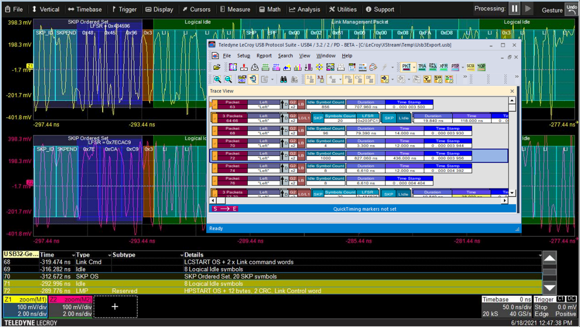
Figure 1. USB 3.2 electrical decoding with ProtoSync view of protocol packets, captured using TF-USB-C-HS. Click on any image to enlarge it.
Figure 1. USB 3.2 electrical decoding with ProtoSync
view of protocol packets, captured using TF-USB-C-HS.
Click on any image to enlarge it.
In a USB-C connector, link training for USB 3.1/3.2 is negotiated using an LTSSM (Link Training and Status State Machine) through electrical signaling on the TX1/RX1 and TX2/RX2 connector pins. Link training must be completed on the link before high-speed data transactions can occur.  One problem you might encounter during link training is a failure to train to USB 3.2 Gen 2 specifications. Teledyne LeCroy customers report that most system-interoperability problems are caused by either link-training or sideband-negotiation failures, which in turn can result from an electrical problem, a digital problem or a combination of both. 

TF-USB-C-HS enables you to probe all points on the USB-C connector to measure and analyze live links. The insertion-loss profile of the included cable and coupon is tuned to be the equivalent of a golden 0.8-m USB Type-C cable, so you can replace a 0.8-m cable with the coupon and not experience any difference in link performance. The coupon also has a loop to allow a current probe to make load-current measurements, and the HS version is compatible with Teledyne LeCroy DH Series probes for making high-speed differential measurements.

We'll show how to trigger, acquire and decode to find problematic link training packets synchronous with the physical-layer electrical waveforms, so you can tell if the source of your interoperability  problem is electrical, logical or both.

06 June 2022

What Happens When You Connect a USB-C Cable

The USB Type-C® connector is designed to be very simple for the user to use: you insert it in either orientation, and a multitude of services just “work”. Though simple to use, it is a complicated connector to program and test, with a very complex system of protocols behind it. There is USB power delivery (USB-PD) and multiple rates of USB data delivery from USB 2.0 through USB4®, specified by the USB Implementers Forum (USB-IF®). There are protocols other than USB, such as DisplayPort™, High-Definition Multimedia Interface (HDMI™), Peripheral Component Interconnect Express (PCIe®), Base-T Ethernet and Thunderbolt™. 

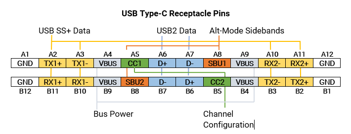
So, what actually happens when you connect a USB-C cable? To understand that, first let’s take a look at the signals and pin assignments in the USB-C connector receptacle (Figure 1).

Figure 1: The USB-C receptacle pin assignments showing the key signals used for device-to-device communications. Related pins have matching color overlays.

Figure 1: The USB-C receptacle pin assignments showing the key signals used for device-to-device communications. Related pins have matching color overlays.

02 August 2021

Debugging L1 Substates Timing Errors with CrossSync PHY for PCIe

Figure 1: CrossSync PHY for PCIe lets you easily map the electrical to the protocol layer of L1 substate events.
Figure 1: CrossSync PHY for PCIe lets you easily map the
electrical to the protocol layer of L1 substate events.
Debugging the L1 substates used for PCIe® power management has been a real pain point for engineers, especially those using the M.2 form factor. The L1.1 and L1.2 substates allow you to take a PCIe link to a deeper power savings state than L1 alone. L1 is entered by either of two mechanisms, an ASPM message or a Power Management message, but in both cases the net effect is that the link goes into electrical idle. Unlike conventional L1, a clock request (CLKREQ#) signal is used to enter and exit the L1 substates. Upon entry, the device or host deasserts the clock request line. By saying, “I don’t require a clock anymore,” the clock can be turned off for additional power savings. Upon exiting the L1 substates, the CLKREQ# is asserted and the reference clock resumes.

26 July 2021

Anatomy of a PCIe Link

Figure 1: A PCIe link between root complex and end point. Each device has its own transmitter and receiver.
Figure 1: A PCIe link between root complex and end point.
Each device has its own transmitter and receiver.
Peripheral Component Interconnect Express (PCIe®) is a high performance, general-purpose input/output (I/O) interconnect designed for a wide variety of computing and communication platforms. Recent iterations of the standard take advantage of high-speed serial technology, point-to-point interconnects, switch-based technology, and packetized protocol. They rely heavily on link negotiation and link training, so much so that being able to capture and view dynamic link behaviors is essential to debugging PCIe devices. Nevertheless, it remains a pain point for PCIe engineers. Why is it so difficult? To start, let’s break down the PCIe architecture to understand what is going on.

15 March 2021

The Important Difference Between ProtoSync™ and CrossSync™ PHY

Figure 1: CrossSync PHY captures everything from physical through protocol layers at once.
Figure 1: CrossSync PHY captures everything from
physical through protocol layers at once.
With the recent release of our new CrossSync™ PHY for PCI Express® product, some of you may be wondering how it’s any different than ProtoSync™ for PCIe®, which has been around for quite a few years.

ProtoSync is an option for Teledyne LeCroy oscilloscopes with bandwidths that support high-speed serial data analysis. We’ve released ProtoSync options for PCIe, USB, SAS/SATA and Fibre Channel. ProtoSync links the same Protocol Analysis Suite software that is used with our protocol analyzers to the oscilloscope application, so that you can see physical layer decodings in the familiar PETracer and BITracer views right next to the decoded analog waveform. 

CrossSync PHY differs from ProtoSync in the three, significant ways:

11 January 2018

Gearing Up for PCIe 4.0 Electrical Compliance Test

Figure 1: A key element in PCIe 4.0
compliance test is a high-bandwidth,
real-time oscilloscope (shown is the
Teledyne LeCroy LabMaster 10Zi-A)
Armed with some of the background information and history on PCIe 4.0 electrical compliance testing, we're now ready to look at just what it takes in terms of test equipment to determine compliance for a PCIe 4.0 device. With the increase in data-transfer rate from 8 Gb/s in PCIe 3.0 to 16 Gb/s in PCIe 4.0, so too have the test equipment requirements advanced.

30 January 2015

Plan For Successful USB Compliance Testing (Part III)

In USB 3.0 link-layer compliance test, all logical states of the LTSSM come into play
Figure 1: In USB 3.0 link-layer compliance test,
all logical states of the LTSSM come into play
In Part I and Part II of this series on USB compliance test, we've looked at some of the basic information on compliance testing and at some aspects of physical-layer test, respectively. In this third part of the series, we'll turn our attention to USB 3.0 link-layer testing.