 |
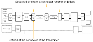
| Figure 1:Automotive Ethernet electrical compliance test is defined at the connector of the transmitter |
First, a quick digression: Where in a typical Automotive Ethernet channel is the electrical compliance testing to take place? Referring to Figure 1, there is a PHY chips in both the transmit and receive outputs. Also shown is a low-pass filter, common-mode choke, connectors, and wiring. All of this is replicated at both ends of the channel.
Electrical compliance testing is defined at the connector of the transmitter. That would be the point shown in Figure 1 that follows the low-pass filter and common-mode choke. Channel and connector recommendations are defined in another document. But all of the electrical compliance testing is to be conducted at the transmitter connector.
 |
| Figure 2: The IEEE 802.3 standard prescribes these five test modes for 100Base-T1 compliance. |
The five modes shown in Figure 2 will all comprise different signal conditions, such as long strings of ones or or minus ones, or distortion, that wouldn't typically be seen in a real-world data transmission. But they're going to quickly reveal what your implementation can and cannot handle.
Test mode #1 detects transmit droop. The waveform is essentially a square wave, defined in the specification as N +1 symbols followed by N -1 symbols. For this test, the symbol period must be at least 500 ns in duration. At a signal rate of 100 Mb/s, at least 34 symbols will be transmitted in that 500-ns span.
Test mode #2, which quantifies transmit jitter in the DUT's master mode, appears as a sine wave. Thus it is simply a repeating sequence of -1, +1, -1, +1, and so on. It is essentially a 33.333-MHz clock signal.
 |
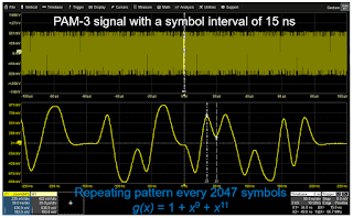
| Figure 3: 100Base-T1's test mode #4 is a PAM-3 signal with a symbol interval of 15 ns. |
Distortion is the object of test mode #4. Mode #4 is a PAM-3 signal with a symbol interval of 15 ns (Figure 3). Note that there is a pattern that repeats every 2047 symbols, a figure that's defined by the polynomial in the test specification.
Finally, test mode #5 for power spectral density and peak differential output is much like mode #4, except mode #4 has that repeating pattern whereas mode #5 is random PAM-3 data with the same symbol interval of 15 ns. Again, there is no discernible difference to the naked eye between modes #4 and #5.
As to the generation of these test mode signals, each PHY silicon vendor incorporates a "backdoor" method of modifying the necessary registers to enter each test mode. These methods are often not publicly available and the methods vary somewhat from vendor to vendor. The best approach is to ask your PHY vendor how to generate the test modes.
In upcoming posts, we'll begin delving into the various Automotive Ethernet electrical compliance tests in greater detail.
2 comments:
What happens when setting the PHY into one of the test modes?. Are signals automatically triggered to be send on the bus or What kind of communication is expected here? to be able to see waveforms in the oscilloscope.
From Product Line Manager Bob Mart:
When the PHY is set into a Test Mode it will continue to transmit that test pattern indefinitely until the PHY register is re-written or the device is powered off. What the DUT sees on the Rx from another device will not have any impact on what the DUT is transmitting.
Post a Comment