| Figure 1: Jitter is short-term variation of a signal with respect to its ideal position in time |
You need to test, we're here to help.
You need to test, we're here to help.
23 December 2013
Back to Basics: Jitter
18 December 2013
Oscilloscope Basics: Trigger Holdoff
As discussed in an earlier post, triggering is the means by which we can coax an oscilloscope into showing us what we're looking for in an input signal, and indeed even simply to display it in a stable fashion. Two of the most basic triggering types are edge triggers and pattern triggers. The latter applies to mixed-signal instruments, allowing users to trigger on a logical combination of analog and digital inputs.
12 December 2013
Back to Basics: Probes (Part IV)
 |
| Figure 1: An example of differential probes measuring from test point to test point. |
04 December 2013
Back to Basics: Probes (Part III)
 |
| Figure 1: Active oscilloscope probes sport high resistance and low capacitance at their tips, but terminate into a scope's 50Ω input. |
27 November 2013
Video: Zooming In On Waveforms
Many modern oscilloscopes offer the ability to zoom in on select portions of a waveform trace, allowing users a much more detailed look at whatever anomalies may (or may not) be present. Zooming is a handy feature on any oscilloscope, but it's even handier if you happen to be using a Teledyne LeCroy HDO. These instruments bring 12 bits of vertical resolution to the table for even more detail and cleaner, crisper waveforms than any legacy 8-bit oscilloscope.
So, without further delay, here's a short tutorial video on how to implement zoom traces on an HDO.
So, without further delay, here's a short tutorial video on how to implement zoom traces on an HDO.
20 November 2013
Back to Basics: Probes (Part II)
In a previous post, we provided some basic information about oscilloscope probes, including a brief survey of the different types and what can happen when the probe is connected to a DUT. In this installment, let's continue along those lines and take a closer look at passive probes.
13 November 2013
Back to Basics: Probes (Part I)
 |
Figure 1: An example of an active
oscilloscope probe
|
30 October 2013
Oscilloscope Basics: Controlling an Oscilloscope (Part II)
 |
| Figure 1: An example of a touch screen-equipped oscilloscope. |
23 October 2013
Oscilloscope Basics: How to Set Up and Use Cursors
As a follow-up to a recent post with an oscilloscope front-panel tour, we want to dig a little deeper into one aspect of controlling the instrument, and that's how to set up and use cursors. But instead of describing it in prose, it makes more sense to show you. So enjoy this brief tutorial video that will get you started with cursors! We're demonstrating on a Teledyne LeCroy HDO4054, but most of what we're showing you translates to other manufacturer's instruments.
16 October 2013
Going From FFTs to Spectrum Analysis
 |
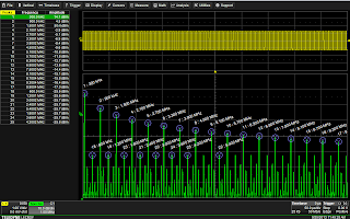
| Figure 1: Spectrum Analyzer software for the HDO series oscilloscopes provides an intuitive user interface |
09 October 2013
Waveform Generator Tricks: Pulse-Width Modulation
 |
| Figure 1: Teledyne LeCroy's WaveStation waveform generator |
02 October 2013
Oscilloscope Basics: Controlling An Oscilloscope (Part I)
 |
| Figure 1: Front of HDO4054 oscilloscope |
25 September 2013
Back to Basics: What is an FFT?
 |
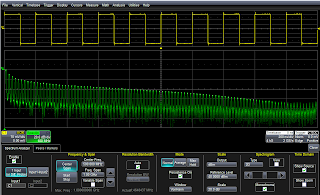
| Figure 1: An FFT of a 300-kHz square wave. |
19 September 2013
Back to Basics: Creating Pulsed Waveforms
 |
| Figure 1: The Pulse waveform dialog box. |
10 September 2013
Don't Just Trigger, But Trigger Smart
 |
| Figure 1: The runt pulse and non-monotonic edge anomalies in this signal are not apparent with a simple edge trigger. |
30 August 2013
Oscilloscope Basics: Setting Up FFTs
 |
| Figure 1: Capture time determines the frequency resolution, Δf. |
15 August 2013
Waveform Generators, Arbitrary and Otherwise
 |
| Figure 1: Teledyne LeCroy's ArbStudio 1104 is a four-channel, 16-bit arbitrary waveform generator with a maximum interpolated sampling rate of 1 GS/s. |
23 July 2013
Back to Basics: Differential Probing
 |
| Figure 1: Emitter voltage measurement in simplified schematic view |
09 July 2013
The Realities of Oscilloscope Probes
 |
Figure 1: Teledyne LeCroy's ZS2500
|
26 June 2013
Back to Basics: Sequence Mode
 |
| Figure 1: Sequence mode enables fast trigger rates and optimizes memory usage by ignoring dead time. |
18 June 2013
Back to Basics: Random Interleaved Sampling
 |
| Figure 1: This image illustrates the general principle underlying RIS. |
10 June 2013
Oscilloscope Basics: Sampling Rate
one of the topics covered is sampling rate. Let's do a somewhat deeper dive on that topic and look at what sampling rate means to oscilloscope users.
29 May 2013
An Overview of Oscilloscope Banner Specs
"Banner specs" is a term that oscilloscope makers use often. If you've ever met with one of the vendors' salespeople, you're likely to have heard it. But what are banner specs and what do they mean to you?
17 May 2013
Oscilloscope Basics: Triggering
At some point, it's likely you've had the experience of capturing a waveform on your oscilloscope only to see a wildly unstable trace displayed on the screen. Chances are that you hadn't adjusted the triggering correctly. Let's take a brief look at what triggering is and why it's important in an oscilloscope. Trigger modes determine when the oscilloscope acquires and what is displayed.
05 April 2013
The Making of 12-Bit Scope Hardware
In many applications, the accuracy of a true 12-bit oscilloscope is not only desirable, but necessary. Going forward, this will become the case more and more often. When choosing one, it's a good idea to peek under the covers and gain a little insight into how the instrument operates. Having discussed in an earlier post the advantages of oscilloscopes with 12-bit vertical resolution, let's look at the ways in which that resolution is accomplished in hardware.
01 April 2013
Oscilloscope Basics: Oscilloscope Bandwidth
Among the most important basic specifications of a digital oscilloscope is its bandwidth. Knowing a bit about bandwidth and the influences on the specification can be very helpful in selecting the right oscilloscope for your application. This post will cover some fundamental aspects of oscilloscope bandwidth.
28 March 2013
Zero in on Power Analysis
Given the emphasis on "green" initiatives, in which anything and everything is touted as "energy efficient," there's been lots of chatter about low-power design. Naturally, much attention is focused on switched-mode power supplies, power devices, and power-conversion circuitry of all kinds. This is where a lot of power efficiency is either lost or gained, depending on how carefully you approach the design task. You know, a milliohm here, a milliohm there, and pretty soon you're talking about real voltage drops that are going to affect the performance of a power-distribution system.
15 March 2013
Spectrogram Display Is Another Tool in the SI Shed
14 March 2013
Check Constellation Diagrams for Digital Data Integrity
Data-communication systems that rely on quadrature signal generation to phase-encode data can run into a number of signal-corrupting snags. These can include things like Gaussian noise, non-coherent single-frequency interference, phase noise, and attenuation in the channel and/or receiver, to name a few. But did you know that you can use your digital oscilloscope to diagnose problems like these?
You Can’t Eliminate Noise You Can’t Measure
Subscribe to:
Comments (Atom)