You need to test, we're here to help.

You need to test, we're here to help.
Showing posts with label edge trigger. Show all posts

13 June 2022

Oscilloscope Basics: Cal Out and Aux Out

Figure 5. New PCIe 6.0 compliance pattern signal.
Fig. 1: Cal Out and Aux Out 
provide many useful outputs.
Oscilloscopes are generally thought of in terms of the signals that are input to them, but even oscilloscopes that are not equipped with function/signal generators can usually output some useful test signals.

Nearly all oscilloscopes have a Cal Out (calibration output) terminal on the front. Most Teledyne LeCroy oscilloscopes also have an Aux Out (auxiliary output) connector on either the front or back, depending on  model. Both outputs provide configurable signals that can assist you to compensate probes and attenuators, test frequency response, trigger waveform acquisition and coordinate multiple test instruments.

16 May 2022

Oscilloscope Basics: External, Line and Fast Edge "Triggers"

An oscilloscope trigger synchronizes the oscilloscope timebase to the input signal so that the displayed trace is stable. In digital storage oscilloscopes, while the digitizer runs continuously converting analog voltage/current inputs to digital values, it is the trigger event that defines the “acquisition window,” marking the point where data is stored to acquisition memory, locking the signal data for display, measurement and further processing. 
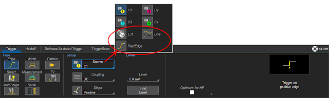
Figure 1: The trigger setup showing the possible choices for the trigger source.

Triggers are set to fire based on the state of a trigger source waveform. What are commonly known as External, Line and Fast Edge "triggers" are not really different trigger types, per se, but alternative trigger sources.  Figure 1 shows the typical setup options for an Edge trigger, the most commonly used trigger type.  With Edge triggering, the oscilloscope is triggered when the source waveform crosses a user-defined threshold level and slope.  Usually, the source will be analog input channel C1-Cn. However, three other sources can be used to initiate an Edge trigger: an Ext(ernal) input, the Line (mains) power and, on some oscilloscopes, the built-in Fast Edge signal. 

04 January 2022

Oscilloscope Basics: Stabilizing Waveform Display, Pt. 1

Figure 1: A free running oscilloscope starts each acquisition at a different point on the waveform, resulting in an unstable display.  A triggered oscilloscope starts each acquisition at the same point on the waveform, resulting in a stable display.
Figure 1: A free running oscilloscope starts each
acquisition at a different point on the waveform,
resulting in an unstable display.  A triggered oscilloscope
starts each acquisition at the same point on the
waveform, resulting in a stable display. 
An unsynchronized, unstable oscilloscope display is useless for making measurements, but proper triggering can synchronize the oscilloscope sample clock to specific waveform events so that the acquired waveforms appear stable on the display.  Let’s look at why signals can appear unstable and what to do about it.  

Oscilloscopes are sampling devices; they sample the incoming signal at a uniform rate.  The timing of a signal applied to the input of an oscilloscope is most probably asynchronous with the oscilloscope’s sampling clock.  If the oscilloscope timebase is allowed to run free—that is, not synchronized to the timing of the input signal—then each oscilloscope acquisition potentially begins at a different point on the input waveform, as shown in Figure 1.

18 December 2013

Oscilloscope Basics: Trigger Holdoff

As discussed in an earlier post, triggering is the means by which we can coax an oscilloscope into showing us what we're looking for in an input signal, and indeed even simply to display it in a stable fashion. Two of the most basic triggering types are edge triggers and pattern triggers. The latter applies to mixed-signal instruments, allowing users to trigger on a logical combination of analog and digital inputs.

10 September 2013

Don't Just Trigger, But Trigger Smart

The runt pulse and non-monotonic edge anomalies in this signal are not apparent with a simple edge trigger.
Figure 1: The runt pulse and non-monotonic edge anomalies
in this signal are not apparent with a simple edge trigger.
In an earlier post, we looked at some of the basics of oscilloscope triggering and noted that there are two broad classes of triggers: simple triggers that sense particular characteristics of the input signal (transition edges, pulse widths, and so on), and more complex triggers that let you zero in on more specific attributes of the signal based on timing and amplitude parameters.

17 May 2013

Oscilloscope Basics: Triggering

At some point, it's likely you've had the experience of capturing a waveform on your oscilloscope only to see a wildly unstable trace displayed on the screen. Chances are that you hadn't adjusted the triggering correctly. Let's take a brief look at what triggering is and why it's important in an oscilloscope. Trigger modes determine when the oscilloscope acquires and what is displayed.