You need to test, we're here to help.

You need to test, we're here to help.
Showing posts with label sequential sampling. Show all posts

25 April 2022

Setting Up Your Oscilloscope for EFT Testing

Figure 1: The typical EFT test signal consists of multiple exponential pulses arranged as pulse bursts.
Figure 1: The typical EFT test signal consists of
multiple exponential pulses arranged as pulse bursts.
A third type of electromagnetic compatibility (EMC) testing deals with how devices respond to electrical fast transients (EFT). EFTs are a series of fast, high frequency pulses, often occurring in bursts. These transient events are the result of electrical arcing. EFT pulse bursts occur when a power connection is made or broken, equipment is powered down or circuit breakers are switched. They also occur when inductive loads such as relays, switch contactors or heavy-duty motors produce bursts of narrow high-frequency transients on the power distribution system when de-energized.

The typical compound waveform used for EFT testing is shown in Figure 1.
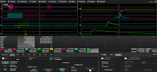
Figure 2: Acquisition of two EFT bursts at 1.25 GS/s, zoomed to show several timing epochs.
Figure 2: Acquisition of two EFT bursts at
1.25 GS/s, zoomed to show several timing epochs.
The pulse waveform for EFT testing is defined by a risetime of 5 ns and a pulse width of 50 ns. These pulses are combined into bursts of 5 to 50 pulses spaced at from 10 to 100 µs (10 to 100 kHz). The bursts are typically spaced as much as 300 ms apart. Figure 2 shows an EFT test signal, with two EFT bursts captured by an oscilloscope on channel 2 sampled at 1.25 GS/s.

The two EFT pulse burst are shown in the upper left-hand trace (the two pink blocks). A series of zoom-on-zoom traces are opened to show several timing epochs. Trace Z2 (second from top left) shows a single burst. The zooms keep expanding the horizontal scale until finally at Z8 (bottom right) we see a single EFT pulse.

Following are six, important things to do to make sure you get the best EFT test measurements from your oscilloscope.

08 March 2021

TDME Primer: Serial Trigger and Sequence Mode Sampling

Figure 1: Sequence mode sampling packs multiple acquisitions into memory with very little “dead time” between them.
Figure 1: Sequence mode sampling packs multiple acquisitions
into memory with very little “dead time” between them.
Sequence mode sampling, also referred to as segmented acquisition, is a sampling mode that divides the oscilloscope’s acquisition memory into a user-defined number of equal length segments. Each segment stores a single acquisition of the triggering event, with as much buffer zone as will fit into that segment, given the total number of segments requested. Only after all segments have been acquired is the data processed and displayed. 

The real power of sequence mode becomes evident when you combine it with intelligent triggers, such as the serial data triggers delivered with TDME options

18 June 2013

Back to Basics: Random Interleaved Sampling

Figure 1: This image illustrates the general principle underlying RIS.
Figure 1: This image illustrates the
general principle underlying RIS.
Modern oscilloscopes come with all kinds of bells and whistles, and users might be tempted to invoke them for all sorts of situations. But not every whiz-bang feature of an oscilloscope is applicable all the time. Rather, some features are great in the right applications but disastrous in others.