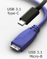
 |
| Figure 1: The USB Type-C connector alongside its Micro-B counterpart |
USB Type-C brings some new and different test challenges due to changes in link configuration and cable detection, among other things. Much of the new complexity comes from the amalgamation of two complementary USB-IF specifications: the Power Delivery 2.0 spec and the USB Type-C spec itself.
The two specifications have become linked together, but this wasn't initially the intent. The higher voltage handling of PD 2.0 was intended for application in legacy USB connectors using FSK signaling. In the meantime, though, interest in FSK signaling vanished. Those interested in implementing the Power Delivery specification have migrated to USB Type-C, with emphasis on very thin notebooks, tablets, and smart phones. Another appealing aspect of the Type-C connector is its universality, which lends itself to the trend toward reduction of e-waste. The mobile market, in particular, is more than ready to settle on a universal charging cable.
As to what is included in the Power Delivery and Type-C specifications, the former defines element such as power delivery discovery, negotiation, and role swapping; biphase mark coding (BMC) and frequency-shift keying (FSK) signaling; and commands for the afore-mentioned alternate modes. The Type-C specification encompasses mechanical and electrical (physical-layer) parameters; the specs for active cables (electronically marked cables with signal-conditioning circuits); and, in a subsection called Functional Extensions, the logical state machines for alternate modes. Unfortunately, at this time there are no plans to merge these two complementary specifications, which would clear up lots of confusion for developers.
 |
| Figure 2: A comparison of the Type-C and legacy USB receptacles |
 |
| Figure 3: Comparing the Type-C receptacle and Type-C plug |
Referring again to Figure 3, pin A5 of the Type-C cable plug always carries the Configuration Channel (CC), which handles discovery, configuration, and management of connections across a Type-C cable. Additionally, if the cable is an electronically marked cable, the VCONN line, used for powering devices, is always on pin B5. There is only one set of SuperSpeed serial data (D+ and D-) pins. The extra pins in the cable plug are there only to support alternate modes. No matter which side of the plug is facing up/down when inserted into the receptacle, it will always use the same pins for USB connections. It is the receptacle's job to adjust its pinout to match that of the cable.
As alluded to above, USB Type-C cables come in two flavors: electronically marked (or E-Marked) and unmarked. Unmarked cables have a chip embedded on the CC line, enabling the downstream-facing port (DFP) to ping the cable, which answers back with its capabilities. Marked cables give you power-handling capability of up to 5 A@20 V, while unmarked cables handle only up to 3 A@20 V. E-marked cables break down further into passive and active varieties; the latter include signal-conditioning circuits that serve as repeaters.
In further posts on this topic, we'll look more deeply into power delivery, cable detection, and other related subjects.
No comments:
Post a Comment