 |
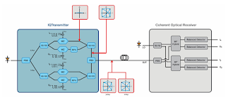
| Figure 1: A representative block diagram of a coherent transmitter and receiver |
First, let's have a quick view of what's found in a coherent communication transmitter and receiver in the form of a block diagram of the standard developed at the Optical Internetworking Forum (Figure 1). The laser's output feeds directly into the polarization beam splitter, which creates the X and Y polarizations. From there, the X and Y polarized beams move into what are known as the Mach-Zehnder (MZ) modulator arms. Thus, the transmitter modulates the four components of the signal (I and Q for the X and Y polarization planes). This is how the optical signal is generated. After the two polarized signals are created, they are combined once again and launched out of the IQ transmitter onto the optical-fiber link.
 |
| Figure 2: Shown is one possible configuration of a Teledyne LeCroy optical modulation analyzer |
On the right side of Figure 1, we see the coherent optical receiver, where the local oscillator is combined with the incoming optical signal in two 90° hybrid structures. Finally, balanced detectors help convert the optical signal to electrical form. Thereby, we obtain the I and Q components on X and Y polarization planes, respectively. These are the signals provided to the oscilloscope for analysis.
Now we come to the optical modulation analyzer itself. There are a number of OMAs available on the market, and these are essentially in two flavors: real-time based systems and equivalent-time (or sampling oscilloscope-based) systems.
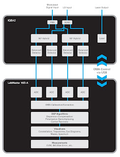
Real-time based OMAs, in which the processing engine is within a real-time oscilloscope (such as Teledyne LeCroy's LabMaster 10Zi-A), are heterodyne configurations that can use an independent laser for a reference local-oscillator input (Figure 2). Three key elements comprise a real-time OMA: a coherent optical receiver, a real-time oscilloscope, and OMA signal-analysis software.
 |
| Figure 3: Schematic of a real-time OMA |
A digital signal processor loaded into the LabMaster oscilloscope's processing engine uses well-known and highly optimized algorithms for extracting the signals from the incoming data streams.
A real-time OMA can measure transmitter signals back-to-back, or measure receiver-side signals after transmission through fiber or some other impairment. Its DSP algorithms are compatible with commercial transceiver designs, so it can be used to characterize a commercial transceiver or transponder and/or ensure its interoperability and compatibility with other systems.
A real-time OMA is the best solution for system measurements, the only solution that can determine a bit-error rate, and also can support non-repeating data patterns. With regard to bit-error rates, there is, of course, dedicated bit-error rate testers that consist of a pattern generator and an error detector. Such equipment compares the incoming pattern with the outgoing pattern on a bit-for-bit basis to determine whether the bits that are transmitted are identical to the bits received. Such functionality is unavailable on sampling or equivalent-time oscilloscopes. On a real-time oscilloscope, the signal acquisition captures a large number of continuous bits with which the instrument can subsequently analyze and measure BER. That ability of the real-time oscilloscope to capture long bit patterns is what facilitates analysis of non-repeating patterns.
Meanwhile, equivalent-time OMAs are well known to optical researchers and have been a de facto industry standard for years. They have their advantages, including the ability to perform highly accurate measurements at high bandwidths and with high dynamic range. They often deliver a high number of points/symbol for finer measurement granularity, and the high vertical bit resolution of equivalent-time oscilloscopes translates into lower quantization noise and the ability to measure higher-order modulation formats.
Alas, equivalent-time OMAs have their downsides, too. They can provide only BER estimates and support only short, repeating data patterns. In general, their phase recovery for system-level experiments comes up short on repeatability. Their strong suit is transmitter characterization, but when it comes to system-level work, they can be found lacking.
Next time, we'll look into how to choose the correct system analog bandwidth, baud rate, and bit coding in an OMA.
No comments:
Post a Comment