 |
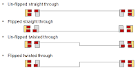
| Figure 1: The four possible states of connection for a USB Type-C cable |
 |
| Figure 2: Shown are the terminating resistors used for USB Type-C cable detection |
Let's say the cable is being plugged in properly, i.e. in un-flipped straight-through fashion as shown in Figure 1. Upon cable plug-in, the DFP and UFP monitor the resistance levels on the CC pins. The DFP attaches pull-up resistors Rp, while the UFP attaches pull-down resistors Rd. In the case of the UFP, both CC pins are connected to ground and only sees this termination on the one CC line that's connected, which would be CC1. Thus, it knows this is the line to use for Power Delivery communications.
Next, the DFP and UFP route the various other signals not shown here. If the cable were flipped over (flipped straight through as in Figure 1), they would see the same Rp and Rd terminations, only they would be on the CC2 line.
 |
| Figure 3: Source-to-sink connection using an E-marked USB Type-C cable |
All of the above assumes a non-E-marked cable. If we look at the same source-to-sink connection but with an E-marked cable, which carries a chip embedded in the CC line that enables the DFP to ping the cable and query it as to its capabilities, we'll see a slightly different setup (Figure 3).
That chip embedded in the cable needs a small amount of power, so this is where the unused CC pin in the receptacle is used to provide it. A change of note in USB Type-C is a new differentiation between VBUS and VCONN power. The former is still used for powering or charging connected devices, while the latter is only for powering of E-marked cables and certain other devices. VCONN provides 5 V @ 200 mA and is initially sourced from the DFP. VCONN power does not pass through the cable to the UFP.
 |
| Figure 4: Deciding whether VCONN comes into play for an E-marked cable |
The end result of this process, in this case, is that the two CC1 pins become VCONN. It is possible that the cable may need VCONN at both ends if it has repeaters or other active components in the plug, so it's up to the cable to propagate power to the far-end plug if necessary. Still, in all cases, VCONN is not passed through the cable but is terminated in the plug's active electronics.
In the next installment in this series, we'll look into dual-role port (DRP) devices, which may act as either provider (source) or consumer (sink).
No comments:
Post a Comment