 |
Figure 1: Power Delivery messaging comprises two types:
Control and Data |
Continuing our review of
USB Type-C and the associated Power Delivery 2.0 (PD) specification, let's now turn to PD message types. Whereas USB was originally conceived as primarily a serial-data interface with limited power-delivery capabilities, the proliferation of power-hungry mobile devices has forced a rethinking of that conception. With PD 2.0 came a much more flexible, and capable, power-delivery functionality for USB. PD messaging is a critical component in this regard.
 |
Figure 2: The multi-drop CC line facilitates
sending targeted Power Delivery messages |
Referring to Figure 1, the Configuration Channel, or CC, pin in a USB Type-C receptacle is the locus for detecting cable orientation. Subsequently, the CC pin becomes the main channel for negotiating and configuring a host of functionality, including power functionality. Both link partners send and receive packets over the CC line. All told, there are 13 control messages and five data messages, and depending on the type, the message may be sent by the source, the sink, or the cable itself. Data messages contain a payload and move in both directions. Some messages can be sent asynchronously by the source, sink, and cable.
 |
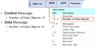
Figure 3: Control and data messages have the same format;
only control messages have zero data objects |
The CC line is considered a multi-drop channel, meaning that a downstream-facing port (DFP) can direct messages to the link partner at the far end of the cable or to each end of the cable. A slightly different frame delimiter makes the distinction. Most of the frames targeted at the upstream-facing port (UFP), the device connected to it, or the DFP, use Start of Packet (SOP) framing. Using SOP prime (SOP') or SOP double-prime (SOP'') framing indicates traffic directed toward the first and second cable plugs, respectively. Either of the latter only occur with E-marked USB Type-C cables.
While most frames are targeted at either the UFP or DFP using SOP framing, some use SOP' or SOP" framing, enabling the host device to talk to the cable. Again, this happens only with E-marked cables.
 |
Figure 4: This table shows all of the different control message
types defined in PD 2.0 |
The basic format of control and data header fields is shown in Figure 3. Both types of messages are in the same format and have 16-bit headers. The main distinction is that control messages have no payload or data objects. Bits 12-14 indicate how many data objects are appended to the message. If this field's value is zero, the message is, by default, a control message. If it's more than zero, it's a data message. Thus, the message type is inferred by the specific value of this "number of data objects" field.
 |
Figure 5: At present, PD 2.0 has only four types of data
messages, with more expected in the future |
Shown in Figure 4 are all of the different types of control messages defined in Power Delivery 2.0. PD 2.0 control messages are essentially used to negotiate power contracts between devices and to initiate role swaps, where a source and sink switch roles. The figure shows the actual bits you would see in the "type" field, which is only a 4-bit field. Control messages comprise the "nuts and bolts" of the Power Delivery protocol.
Data messages, by definition, have at least one data object, each of which is 32 bits long and is transmitted immediately after the header. At present, only four data message types are defined in the standard (Figure 5). More defined data messages may be augmented to the next revision of the Power Delivery specification. In any case, there are a few scenarios in which data messages must be embedded into a PD packet, such as a device making a power request or reporting its capabilities to a host.
A PD 2.0 message header also contains information on the link partners' power roles. This field isn't used very much in practice because upper layers keep track of the devices' power roles. It becomes important, however, when you begin looking at protocol analyzer traces. Once devices start doing role swaps, things get confusing in a hurry.
Another important field is the MessageID field, which is 3 bits long with values from zero to seven. The value increments with each sequential message and is used like a tag in the SCSI protocol, allowing a responder to tie an acknowledgment back to a specific command. Every PD message requires a good-CRC response from the far end, with that good-CRC message having the same MessageID value as the command it acknowledges.
Next, we'll tie it all together with a look at how the Power Delivery protocol works in practice.


No comments:
Post a Comment