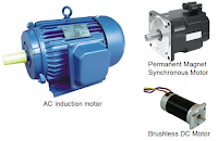
 |
| Figure 1: 45% of worldwide power consumption fuels motors |
For example, to the engineer working for a utility company, "power" is the 50/60-Hz sinusoidal voltage/current power that fuels homes and businesses. The tool du jour in this scenario is a kilowatt-hour meter. But to someone designing a power supply, "power" is about the consumption of MOSFETs or IGBTs during switching, conduction, and/or off states. In this series of Test Happens posts, we'll home in on what's typically referred to as "line" or "mains" power.
There are three key life stages for line power: generation, transmission and distribution, and consumption. Historically, power has been generated at centralized utility "generating plants." These days, there's a trend toward distributed generation from localized sources such as solar PV panels or wind farms.
Transmission and distribution to homes, commercial facilities, and industrial uses sets the stage for consumption. Consumption takes place either directly from the utility line with no power conversion (as with a toaster, for example), or with some manner of conversion through use of power electronics. This can mean AC-AC conversion by variable frequency motor drives, AC-DC conversion by switch-mode power supplies, DC-AC conversion by inverters, or DC-DC conversion.
Historically, power has flowed one way from the central generating station to the consumer. What might surprise some readers is the poor overall efficiency of power delivery, which is about 32%. The input/output efficiency of the generating plant itself is only about 35%, and a bit more is lost in transmission and delivery. Overall, it is an extremely inefficient system.
As a result, the utilities have long focused on reducing the losses they can control, such as those found in transformers and other equipment. Power analyzers were developed to measure efficiencies in these elements of the power supply chain. Transformers are measured for excitation (or core) losses as well as load (copper or I2R) losses as well as overall efficiency. These measurements might be taken as design or validation tests, or the utility might request a report before taking delivery of a transformer to ensure it meets their requirements.
On a worldwide basis, 45% of all generated power feeds motors (Figure 1).
- 9% of that power drives small motors (those up to 750W, which is 90% of all motors)
- 68% drives medium-sized motors (up to 350kW, which is 9.9% of all motors)
- 23% drives large motors (up to 1000kW; 0.03% of all motors)
 |
| Figure 2: Testing a motor on a test stand |
In those bygone days before 1990, motors were typically tested through use of a test stand (Figure 2). The focus of such testing was those medium-to-large-sized motors and would have been accomplished using a load cell, dynamometer, or power analyzer. These rudimentary tests were typically static load tests with constant load, speed, and torque. Instrumentation would acquire speed and torque sensor signals, enabling calculation of input to output power all the way to the output of the motor shaft. One could arrive at the motor's efficiency in this manner, but only for one speed, load, and torque condition.
Meanwhile, there's been a revolution in the world of power electronics and power conversion. Unlike the 1980s, when switch-mode power supplies were all the rage, motor drives are ubiquitous these days. They've steadily increased in design complexity and power level over the years (Figure 3). Today, we see very complex drives, up to and including the regenerative systems found in the propulsion systems of electric and hybrid vehicles, for example.
A number of tools lend themselves to drive and/or motor analysis. The aforementioned traditional AC power analyzer can calculate only static (steady-state), mean power values. Some instruments in this class do not integrate motor torque and speed data.
A general-purpose, four-channel, 8-bit oscilloscope is useful on the control side of the equation; most modern instruments carry serial trigger/decode software for that purpose. Such an instrument is also useful for testing the device losses of a single power semiconductor. However, most four-channel oscilloscopes lack enough channels and/or resolution to sort out three-phase systems.
More channels are more useful in testing motor drives. Teledyne LeCroy's MDA800 Motor Drive Analyzers bring eight analog input channels to the table for complete three-phase power analysis from motor drive input through motor mechanical output. The instruments present results in an easy-to-use numerical table format. With such an instrument, one may perform control debugging, motor integration, and transient or dynamic power analysis.
In upcoming posts in this series, we'll dig deeper into what we really mean when we discuss AC or line voltage, current, or power.
 |
| Figure 3: Motor drives have steadily improved over the years |
A number of tools lend themselves to drive and/or motor analysis. The aforementioned traditional AC power analyzer can calculate only static (steady-state), mean power values. Some instruments in this class do not integrate motor torque and speed data.
A general-purpose, four-channel, 8-bit oscilloscope is useful on the control side of the equation; most modern instruments carry serial trigger/decode software for that purpose. Such an instrument is also useful for testing the device losses of a single power semiconductor. However, most four-channel oscilloscopes lack enough channels and/or resolution to sort out three-phase systems.
More channels are more useful in testing motor drives. Teledyne LeCroy's MDA800 Motor Drive Analyzers bring eight analog input channels to the table for complete three-phase power analysis from motor drive input through motor mechanical output. The instruments present results in an easy-to-use numerical table format. With such an instrument, one may perform control debugging, motor integration, and transient or dynamic power analysis.
In upcoming posts in this series, we'll dig deeper into what we really mean when we discuss AC or line voltage, current, or power.
No comments:
Post a Comment