High-speed serial links such as those used in DDR4 and DDR5 are subject to a variety of signal degradation challenges. Insertion losses, frequency dependent attenuation and inter-symbol interference (ISI), as well as others, are among the most commonly encountered sources of signal degradation.
Figure 1 shows how reflections can cause ISI on a rectangular pulse. When a rectangular pulse is transmitted, it suffers distortion which is apparent when it reaches the receiver. It may be broadened due to group delay dispersion because different frequency components of the signal propagate along the signal path at differing velocities. In addition, there may be echo pulses, due to impedance mismatches in the channel. These mismatches cause reflections that propagate back and forth over the channel and appear as these echoes where subsequent bits should be.
Generally, these signal losses can be compensated for using
any of several equalization techniques. The commonly used equalization
techniques are feed forward Equalization (FFE), Continuous Time Linear
Equalizations (CTLE), and Decision Feedback Equalization (DFE). FFE and CTLE basically filter the signal to
increase the amplitude of high frequency signal components eliminating the
frequency dependent attenuation of the signal path.
 |
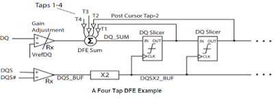
| Figure 2. Example of a 4-tap DFE equalizer. |
The DQ signal goes through an analog gain adjustment stage
and is applied to a summer. The output
of the summer goes to the first slicer, implemented as a flip flop, where the
logical state (0 or 1) is determined, and the signal is delayed by one clock
cycle. The signal propagates through a
total of four such slicers. The output
of each slicer is weighted by individual tap weights T1 – T4 and is then fed
back to the summer where the weighted sum is subtracted from the DQ signal. The feedback returns the scaled copies of the
last four bits to the input. This
effectively removes ISI from the input. Since the signal is quantized and noise
component is ignored in that process it is not propagated. The clock is required to assure correct
timing of the summation components.
DDR5 specifies the use of Decision Feedback Equalization or
DFE. DFE is used rather than FFE or CTLE
because it provides equalization without increasing the noise level on the
signal. FFE and CTLE basically boost the high frequency response of the channel
to compensate for the channel’s frequency dependent attenuation. The boost is the result of an analog filtering
process. This has the effect of increasing noise and noise-like effects like
crosstalk, as well. The slicer stages in
DFE quantizes the signal ignoring the noise voltage, and it does not propagate
noise to the output of the equalizer. So, it provides high frequency boost
without the noise.
In addition to the excellent noise performance, DFE is
relatively inexpensive to implement.
The DFE equalizer has one possible negative characteristic:
if one of the slicers makes an incorrect determination, then the output will
see a burst of errors until the sequence is cleared. This is a not common event, especially if the
data sequence is random.
The DDR Debug Toolkit includes tools for setting up DFE. The
weight of each tap can be entered manually, or the DFE can be “trained”. The training process will automatically
determine and enter the correct tap weights.
To learn more about DDR testing and our DDR solutions, watch the on-demand webinar, DDR4/5 & LPDDR4/5 Probing and Debug Solutions.
Also see:
Which Virtual Probing Method to Use?
Isolating DDR Read and Write Operations
Removing Reflections from DDR Signals Probed Mid-Bus

No comments:
Post a Comment