 |
| Figure 1: Shown is an overview of the PCIe 4.0 link-equalization response test |
There are two link equalization tests: Transmitter initial Tx equalization and transmitter link equalization response. The latter is more complex and thus more interesting. The former is quite similar to the transmitter preset test described in an earlier post, except instead of using a toggle button on the test fixture board to force the transmitter into each preset, you have to negotiate it into each preset using the PCIe protocol, and then perform the preset test.
 |
| Figure 2: This is the test setup for the transmitter link-equalization response test |
Note that the preset request from the BERT and the DUT's response are both being acquired by the oscilloscope. We want to determine how long that response takes to happen and also ensure that the emphasis preset changed to the correct value. That's something you can only do with an oscilloscope, because you must actually observe the physical-layer emphasis change to evaluate the change in the analog signal shape. The oscilloscope uses the preset feature in the SigTest software from PCI-SIG to accomplish this.
 |
| Figure 3: Shown is an example of a Tx link-equalization response test |
The transmitter link equalization response test setup appears in Figure 2. The signal out of the BERT's pattern generator is split so that it is sent to both the DUT's receiver and also into two oscilloscope input channels. The signal coming out of the DUT at Tx Lane 0 is also split to feed both the oscilloscope and the BERT's error detector, the latter of which permits the BERT to converse with the DUT at the protocol layer. Thus, the oscilloscope acquires both the downstream signal from the BERT to the DUT and the upstream signal from the DUT to the BERT.
 |
| Figure 4: The oscilloscope acquires both the downstream signal from the BERT and the upstream signal from the DUT |
On the oscilloscope, we see two differential signals: the downstream signal from the BERT, and the upstream signal from the DUT (Figure 4). The latter, in orange, is the digital signal from the BERT to the DUT, and somewhere in that data stream is the protocol-layer request to change the Tx emphasis preset from P7 to P4. The blue trace is the signal returning from the DUT to the BERT, and it reflects the actual change in the preset. That change is denoted by the change in the signal's analog shape, and it's rather obvious where that change occurs.
 |
| Figure 5: The protocol-layer decode of the BERT's data stream shows the exact location of the preset change request |
This is where the oscilloscope's protocol-decode capabilities come into play. The oscilloscope decodes the downstream data; the protocol-layer decode appears in Figure 5. We can now see the actual protocol-layer decode of the downstream data from the BERT. The EQ control block (seen in detail at lower right) shows us that in packet 25, the BERT was asking for Tx emphasis preset P7, and that in packet 26 it requested P4. That's the exact point at which the preset change request took place.
 |
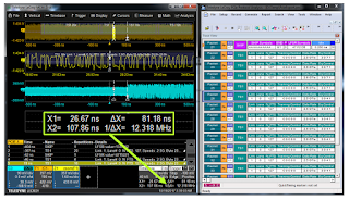
| Figure 6: Knowing the start and end points for the response- time measurements now makes a result easily obtainable |
Figure 6 gives us the measurement of the response time from protocol-layer request to physical-layer Tx emphasis change: 81.18 ns. With a pass/fail limit of 1 μs, this is an easy passing test result. It even gets us well below the desired 500-ns time for the response.
All of the above adds up to a fairly sophisticated test that requires much of the test system's components. Not only does it require an oscilloscope with a real-time bandwidth of at least 25 GHz, that oscilloscope needs to be able to decode the PCIe 4.0 data stream to find the exact point at which the Tx emphasis change request occurred. Then, the BERT must not only have the pattern generator and error detector operating at the right bit rate, but it must also be able to perform the link training and state-machine analysis for all the protocol-level negotiation.
Coming up next is a look at PCIe 4.0 receiver link-equalization testing procedures.
Earlier posts in this series:
Introduction to PCIe 4.0 Electrical Compliance Test
Gearing Up for PCIe 4.0 Electrical Compliance Test
PCIe 4.0 Transmitter Electrical Testing (Part I)
PCIe 4.0 Transmitter Electrical Testing (Part II)
No comments:
Post a Comment