 |
| Figure 1: With an add-in card as our DUT, we will measure the transmit signal at the root complex on the system board |
We'll be using a PCIe 4.0 add-in card as our DUT in these examples, so the add-in card's transmitter is the source of our signal under test. Thus, we want to measure the transmitted signal at the physical location of the root complex on the system board, where it will have traversed the entire channel, including a 20-dB worst-case loss on the system board itself (Figure 1).
 |
| Figure 2: Add-in card DUTs reside in a test fixture from PCI-SIG |
To begin, the add-in card is installed in a test fixture (Figure 2). As noted in an earlier post, PCIe 4.0 test fixtures will be available directly from PCI-SIG; note that these are new fixtures with features different from those on older PCIe 3.0 test fixtures, which cannot be deployed for 4.0 testing.
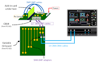
Referring again to Figure 2, our DUT is the add-in card shown in light green at top left, while the dark green boards are the test fixtures available from PCI-SIG. The 15 dB of the total system board loss is simulated in the ISI fixture at lower left. The remaining 5-dB loss of the total 20-dB worst-case system board loss is simulated by embedding an S-parameter package model into the waveform using the oscilloscope's software.
 |
| Figure 3: Shown is the test setup for add-in card transmitter signal quality |
For transmitter equalization preset selection, we must acquire at least one 1.6-million-UI waveform at each preset. The test fixture gives you a means of selecting presets by simply pressing a button on the fixture. Teledyne LeCroy offers its TF-PCI4-CTRL compliance base board (CBB) automation controller, which, in concert with QualiPHY PCIe4 compliance test software, takes over control of these preset selections.
The oscilloscope and its test-automation software (Teledyne LeCroy's LabMaster 10Zi-A and QualiPHY PCIe4-Tx-Rx, respectively) run the SigTest software that is forthcoming from PCI-SIG. In turn, SigTest runs the preset and signal-quality tests on the acquired waveforms. SigTest doesn't run especially fast, so the signal-quality test can be time consuming. The LabMaster 10Zi-A alleviates this through its server-class motherboard with a 20-core CPU, which runs many instances of the SigTest software in parallel to reduce test time from as much as three hours to no more than about 20 minutes.
 |
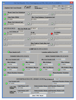
| Figure 4: SigTest provides a pass/fail test report |
For the signal-quality test, the DUT has to pass only at one preset. Our preliminary findings are that for PCIe 4.0, the "golden preset" that typically produces a good result is either P5 or P6. Veterans of PCIe 3.0 might recall that for that revision of the standard, the "golden preset" tended to be P7 or P8.
The pass/fail signal-quality test results comprise an eye-diagram plot and a report of jitter statistics, eye diagram transition and non-transition statistics, and extrapolated eye-height statistics (Figure 4).
That concludes our look at the PCIe 4.0 transmitter tests. Note that these tests used only the oscilloscope. Next time, we'll turn to transmitter link equalization testing, when we get to fire up the signal generator and bit error-rate tester.
Earlier posts in this series:
Introduction to PCIe 4.0 Electrical Compliance Test
Gearing Up for PCIe 4.0 Electrical Compliance Test
PCIe 4.0 Transmitter Electrical Testing (Part I)
No comments:
Post a Comment